


6
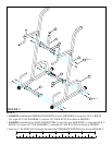
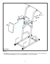
STEP 2:
0
1
2
345
6
1/2 1/2 1/2 1/2 1/2 1/2
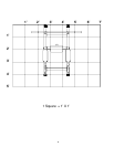
FIGURE 2
• LOOSELY assemble the UPPER BACK SUPPORT (4) to the VKR SIDES (3) using four 3/8 X 3” BOLTS
(10), eight 3/8” FLAT WASHERS (7), and four 3/8” LOCK NUTS (9) as shown in FIGURE 2.
• LOOSELY assemble the two BASE CONNECTORS (1) and (16) to the VKR SIDES (3) using eight 3/8 X 3”
BOLTS (10), sixteen 3/8” FLAT WASHERS (7), and eight 3/8” LOCK NUTS (9) as shown in FIGURE 2.
7
10 3/8 X 3”
9
7
3
14
4
9
7
16
1
10 3/8 X 3”
• Insert one 2” SQ. END CAP (14) into the the end of the UPPER BACK SUPPORT (4) as shown in FIGURE 2.