


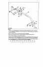
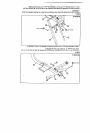
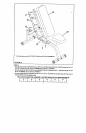

FIGURE 3
I !
1/2 X3"
3/8
STEP 3:
¯ Snap two 3 X 2" GUIDE INSERTS (15) into the ends ofthe WOLFF SLEEVE (7) =~s-shown in HGURE
¯
In~er~ 3/8" SPRING PIN ASSEMBLY (11) into the spring pin barrel on WOLFF SLEEVE (7) and tighten
securely. See FIGURE 3.
¯
Slide one 4" VINYL CAP (17) over the U-PIN (16) as shown in FIGURE
¯
Slide U-PIN (16) through the bushing on WOLFF SLI~.Wv-E (7) and attach with PAL-NUT
¯
Slide the WOLFF SLEEVE (7) over the BENCH FRAME (3).
¯
Securely assemble the BENCH FRAME (3) to the REAR LEG (1) & the SWIVEL PLATE (2) using two
3" BOLTS (21), two 1/2" FLAT WAS~ (24), and two 1/2" NYLOCK NUTS (26) as shown in FIGURE
¯ Securely assemble the 2 SQ.X 18" TUBE (8) to the BENCHFRAME (3) using two 3/8 X3" BOLTS (19),
3/8" FLAT WASI-~I~S (23), and two 3/8" NYLOCK NUTS (25). See FIGURE 3.
3 [ I I I
1 [ ! ! !
!
0 I ! I I
I ! I ! ! ! I ! I
4