


15
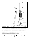
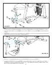
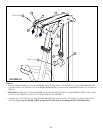
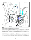
STEP 16:
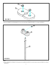
FIGURE 16
37
9
63
3/8 X 1-3/4” 53
• Route the BOOM CABLE (32) over the V-GROOVE PULLEY (39) and the 3-1/2” PULLEY (37) on the LEFT BOOM PLATE
(15) and over the 3-1/2” PULLEY (37) on the RIGHT BOOM PLATE (14) and over the V-GROOVE PULLEY (39) as shown in
STEP 16.
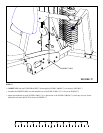
• SECURELY assemble two 2” NYLON SPACERS (56) to the V-PULLEY PLATES (12) and the BOOM PLATES (14 & 15) using
two 3/8 X 2-3/4” BOLTS (55) and two 3/8” LOCK NUTS (63). See FIGURE 15.
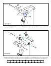
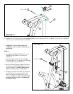
• Assemble one 3-1/2” PULLEY (37) to the PULLEY BRACKET (9) using one 3/8 X 1-3/4” BOLT (53) and one 3/8” LOCK
NUT (63) (Note: Loop the BOOM CABLE around the PULLEY prior to assembling the PULLEY BRACKET.)
15
14
12
63
56
3/8 X 2-3/4” 55
32
39