


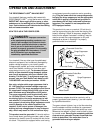
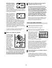
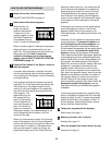
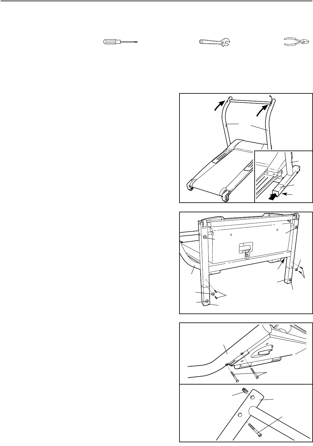
3. Refer to drawing 3a. While another person holds the
Handrails (89), thread Handrail Bolts (111) about 2-3
turns into the two holes in each Handrail. Then, remove
the Handrail Bolts.
Refer to drawing 3b. Pinch the tabs on the Grounding
Bracket (115) so that the tabs will fit into the indicated
hole in the left Upright (110). Then, insert the Grounding
Bracket into the hole as far as possible.
Note: It may be helpful to set the Handrails (89) on the
Uprights (110) and loosely thread a Handrail Bolt (111)
into the left Upright and the left Handrail. Tip the
Handrails, if necessary, to thread in the Bolt. Have an-
other person support the Handrails as you complete the
remaining steps.
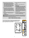
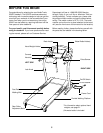
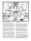
ASSEMBLY
Assembly requires two people. Set the treadmill in a cleared area and remove all packing materials. Do not
dispose of the packing materials until assembly is completed. Assembly requires the included allen wrench
and your own phillips screwdriver , adjustable wrench , and wire cutters .
Note: The underside of the treadmill walking belt is coated with high-performance lubricant. During shipping, a
small amount of lubricant may be transferred to the top of the treadmill or the shipping carton. This is a normal
condition and does not affect treadmill performance. If there is lubricant on top of the walking belt or foot pads,
simply wipe off the lubricant with a soft cloth and a mild, non-abrasive cleaner.
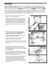
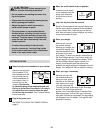
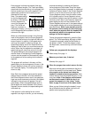
1. With the help of a second person, carefully raise the
Uprights (110) to the position shown.
Refer to the inset drawing. Insert one of the Extension
Legs (88) into the treadmill as shown. Make sure that
the Extension Leg is turned so the Thick Base Pad (90)
is on the bottom. Note: It may be helpful to tip the
Uprights (110) forward as you insert the Extension Leg.
Insert the other Extension Leg (not shown) in the same
way.
1
110
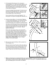
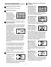
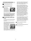
2. With the help of a second person, carefully tip the
Uprights (110) down as shown. Make sure that the
Extension Legs (88) remain in the Uprights.
Attach each Extension Leg (88) with two Base Screws
(86) and a Base Pad (75) as shown.
With the help of a second person, carefully tip the
Uprights (110) back to the vertical position.
Note: One replacement Base Pad (90) may be included.
If a Base Pad needs to be replaced, use the replacement
Base Pad.
86
88
110
110
86
88
90
90
90
90
90
90
2
90
88
110
6
110
111
111
89
115
3a
3b