


7
5
8
5
105
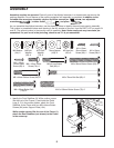
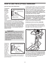
Grease
86
118
119
Axle
86
2
3
24
2
31
3
Lubricate
118
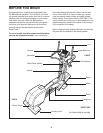
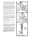
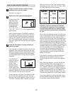
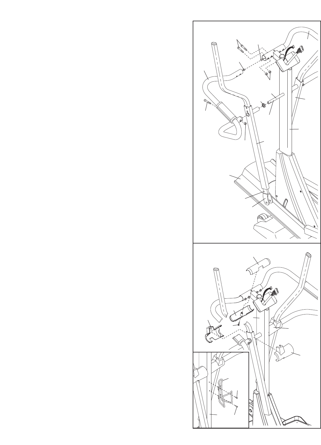
5. Slide a Weld Spacer (119) onto the axle on the left
side of the Upright (2), with the open side of the Weld
S
pacer facing the Upright. Apply a generous amount of
grease to the axle.
Hold one of the Upper Body Arms (118) with one hand,
hold the Upper Body Leg (31) with your other hand,
and slide the Upper Body Arm onto the axle on the left
side of the Upright (2). Next, extend the Upper Body
Leg and apply half of the included high-temperature
lubricant. Then, rest the end of the Upper Body Leg on
the Ramp (3).
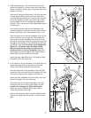
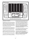
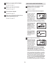
Have another person hold the Left Handlebar (24)
near the Upright (2) as shown. Connect the left Pulse
Sensor Wire (20) to the Pulse Extension Wire (114).
Slide the upper end of the Left Handlebar (24) into the
tube on the front of the Upright (2), while sliding the
lower end of the Left Handlebar onto the axle on the
left side of the Upright. Attach the upper end of the Left
Handlebar with two M8 x 41mm Button Bolts (85) and
two M8 Jam Nuts (86);
be careful not to damage the
Wires (20, 114) as you insert the Button Bolts.
Make sure that the Jam Nuts are resting in the
hexagonal holes in the Left Handlebar. Attach the
lower end of the Left Handlebar with an M8 x 38mm
Button Bolt (105) and an M8 Jam Nut (86).
Attach the other Upper Body Arm (118) and the Right
Handlebar (23) in the same way.
114
20
26
96
25
25
2
26
26
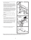
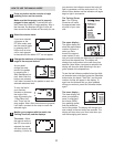
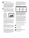
6. Look inside one of the Handlebar Cover Sets (26) and
locate the square tabs connecting the two halves.
Gently lift the tabs and disconnect the halves.
Hold the two halves of the Handlebar Cover Set (26)
around the tube on the left side of the Upright (2). Align
the halves and press them together until they lock.
Attach the other Handlebar Cover Set (26) to the right
side of the Upright (2) in the same way.
Hold the halves of the Upper Handlebar Cover (25)
around the tube on the front of the Upright (2); be
careful not to damage the W
ires (not shown).
Attach the Upper Handlebar Cover with an M4 x
12mm Round Head Screw (96).
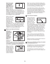
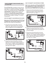
See the inset drawing. Attach the Water Bottle Holder
(108) to the Upright (2) with two M4 x 16mm Screws
(98).
6
98
108
98
2