


6
3
14
1
Grease
48
48
76
7
6
99
99
Tubes
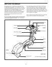
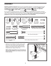
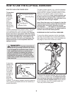
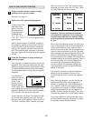
2. Identify the Pivot Axle (14), which is the longer of the
two axles. Slide a Ramp Cover (48) onto an M6 x
1
6mm Patch Screw (76) as shown. Tighten the Patch
Screw into one end of the Pivot Axle. Apply a small
a
mount of the included grease to the Pivot Axle.
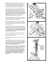
Have a second person hold the two Ramp Spacers
(99) against the sides of the Frame (1) so they cover
the indicated tubes on the Frame. Align the round
tubes on the Ramp (3) with the Ramp Spacers. Make
sure that the Ramp is turned as shown in drawing
3 below.
Insert the Pivot Axle (14) into the Ramp, the
Ramp Spacers, and the Frame. If necessary, use a
rubber mallet to fully insert the Pivot Axle.
Slide the other Ramp Cover (48) onto an M6 x 16mm
Patch Screw (76) as shown. Tighten the Patch Screw
into the open end of the Pivot Axle (14).
Tubes
2
3
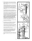
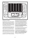
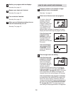
3. Slide an M6 Washer (64) onto an M6 x 16mm Patch
Screw (76).
Tighten the Patch Screw into one end of
the Incline Axle (13). Apply a small amount of grease
to the Incline Axle.
Raise the Ramp (3). Insert the Incline Axle (13) into
the welded tube under one side of the Ramp, through
the motor screw, and then into the welded tube under
the other side of the Ramp.
As you insert the Incline
Axle through the motor screw, make sure that the
motor screw does not turn.
Slide an M6 Washer (64) onto an M6 x 16mm Patch
Screw (76). Tighten the Patch Screw into the open
end of the Incline Axle (13).
13
Grease
Motor
Screw
64
76
3
64
76
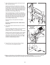
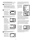
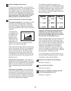
4. Have another person hold the Upright (2) in the posi-
tion shown.
Connect the Upper Wire Harness (115) to the Lower
Wire Harness (42). Insert the connectors on the Wire
Harnesses up into the Upright (2). Carefully pull the
upper end of the Upper Wire Harness to remove
the slack from the Wire Harnesses.
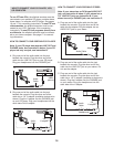
Insert the Upright (2) into the Frame (1). Be careful to
avoid pinching the Wire Harnesses (115, 42). Attach
the Upright with two M10 x 108mm
Button Screws
(70), two M10 Split Washers (73), and two 7.6mm
Spacers (109).
Make sure that the curved sides of
the Spacers are facing the Upright.
Be careful to
avoid damaging the W
ire Harnesses with the
Button Screws. Do not tighten the the Button
Screws yet.
2
115
70
42
1
73
73
109
4
109
Do not pinch
the wire
harnesses
during this
step.
Pull