


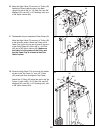
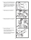
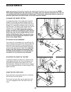
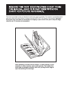

ATTACHING THE ACCESSORIES
The Lat Bar (61), Ankle Strap (10), and Ab Strap (75)
can be attached to the cable at the desired pulley sta-
tion with a Cable Clip (69). For some exercises, the
Chain (67) should be connected between the attach-
ment and the cable with two Cable Clips. Adjust the
length of the Chain between the accessory and
the cable so the accessory is in the correct start-
ing position for the exercise to be performed.
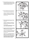
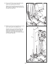
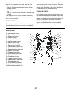
ADJUSTING THE HEIGHT OF THE SEAT
To adjust the height of the Seat (13), loosen the indi-
cated Adjustment Knob (9). Pull out the Knob as far
as possible and slide the Seat Upright (37) to the
desired position. Release the Knob so that it engages
one of the adjustment holes in the Seat Upright. Fully
tighten the Knob.
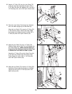
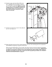
USING THE LEG LEVER LOCK
Some exercises can be performed more comfortably
with the Leg Lever (29) locked.
To lock the Leg Lever (29), turn the Leg Lever Lock
(11) until it engages the Pad Tube (28) on the Leg
Lever.
22
13
9
37
The instructions below describe how each part of the weight system can be adjusted. Refer to the exercise
guide accompanying this manual to see how the weight system should be set up for each exercise. IMPOR-
TANT: When attaching the lat bar, ankle strap, or ab strap, make sure that the accessories are in the cor-
rect starting position for the exercise to be performed. If there is any slack in the cables or chain as an
exercise is performed, the effectiveness of the exercise will be reduced.
61
69
10
67
69
75
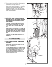
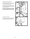
CHANGING THE WEIGHT SETTING
To change the setting of the weight stack, insert the
Weight Pin (39) under the desired Weight (26). Be
sure to insert the Weight Pin until the bent end of the
Weight Pin is touching the Weights, and turn the bent
end downward. The setting of the weight stack can be
changed from 10 pounds to 200 pounds, in incre-
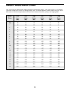
ments of 10 pounds. Note: Due to the cables and
pulleys, the amount of resistance at each exercise
station may vary from the weight setting. Use the
WEIGHT RESISTANCE CHART on page 24 of this
manual to find the approximate amount of resist-
ance at each weight station.
26
39
ADJUSTMENTS
11
28
29