


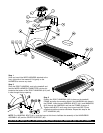
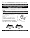
Step 4
Snap together the male and female 10-PIN CONNECTORS protruding
from the top of the RIGHT HANDRAIL (#10) and the underside of the
HANDLEBAR ASSEMBLY (#5). Once connected, feed the excess
cable carefully back into the top of the HANDRAIL. Rest the
HANDLEBAR in position on the VERTICAL HANDRAILS and install the
six SCREWS (#6) and WASHERS (#7) to secure the HANDLEBAR
ASSEMBLY to the two VERTICAL HANDRAILS.
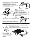
Step 5
Snap the 10-PIN CONNECTOR protruding from the top of the
HANDLEBAR ASSEMBLY (#5) into the
corresponding CONNECTOR in the back of the
DISPLAY CONSOLE (#1). Snap the 6-PIN
CONNECTOR of the extended memory board wire
harness (located in the display console bracket)
into the corresponding CONNECTOR in the back of the
DISPLAY CONSOLE. Install the four SCREWS (#3) in a criss-
cross pattern to secure the DISPLAY CONSOLE to the
HANDLEBAR ASSEMBLY.
Step 6
Place the
HANDRAIL CENTER SUPPORT into position between the two
HANDRAILS and secure it with the four CENTER SUPPORT SCREWS
(#4).
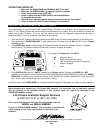
Step 7
Secure the bottom sides of the HANDRAILS to the angled FRAME
BRACKETS using two SCREWS (#13) for each HANDRAIL.
THE SCREWS (#13) MUST BE FIRMLY TIGHTENED BEFORE TIGHTENING THE HANDRAIL BOLTS (#11) TO
INSURE PROPER STABILITY OF THE UPPER TREADMILL.
Step 8
Tighten the HANDRAIL BOLTS (#11) securing the base of each of the VERTICAL
HANDRAILS to the FRAME of the treadmill.
Position the right (#15) and left (#16) HANDRAIL SIDE CAPS into place on the
corresponding HANDRAILS and secure each with two REMOVEABLE RIVETS (#14).
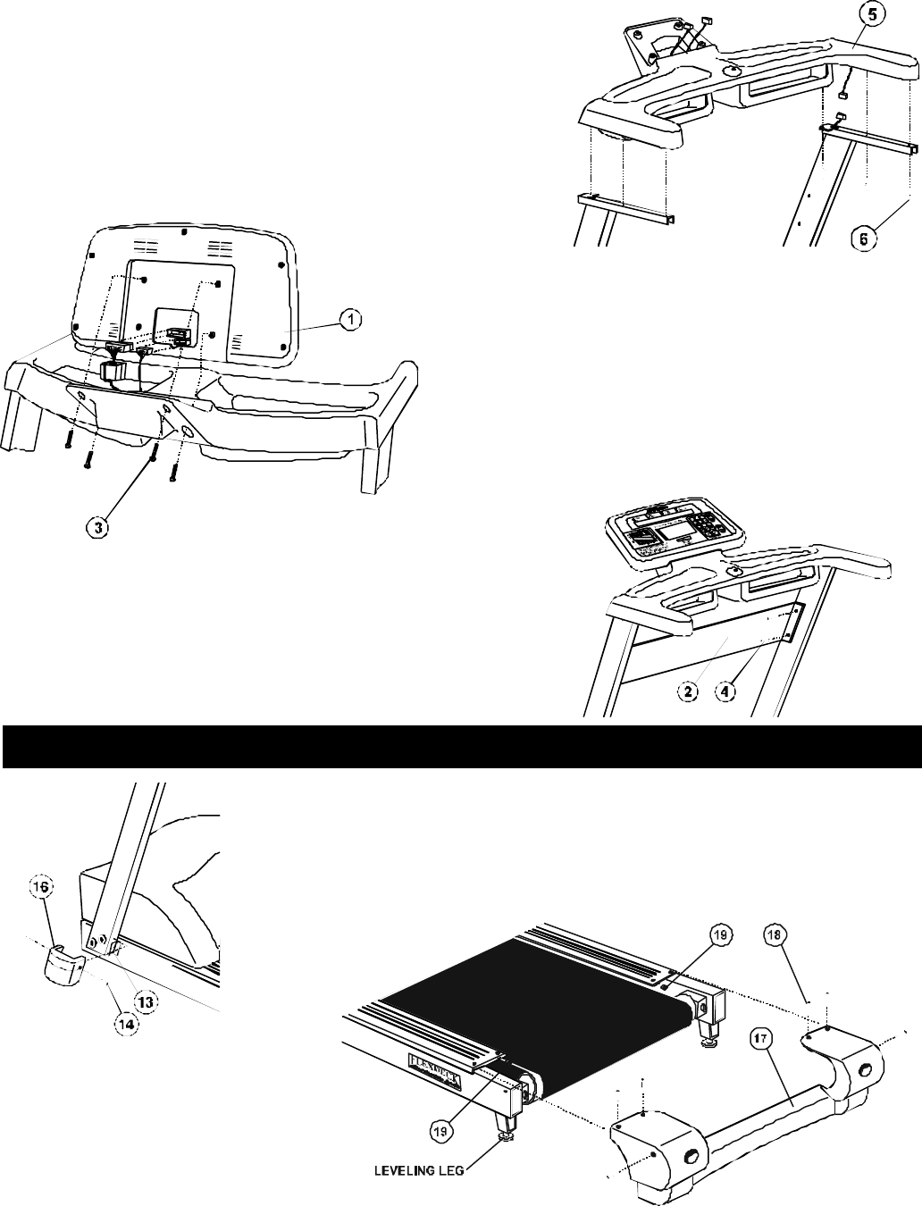
Step 9
Insert the two TINNERMAN CLIPS (#19)
into the slots as shown below. Check
that the holes in the extrusion align with
the holes in the TINNERMAN CLIPS. Set
the ENDCAP (#17) into position and
secure in place with the six ENDCAP
SCREWS (#18).
1 3
X
4 2