


IMPORTANT!
DO NOT DISCARD THE SHIP KIT LOCATED ON TOP OF THE PEDAL LEVERS. ALL NECESSARY COMPONENTS
NEEDED TO COMPLETE THE INSTALLATION ARE LOCATED IN THE SHIP KIT.
IMPORTANTES!
NE JETEZ PAS LE KIT PLACÉ SUR LE DESSUS DES LEVIERS DE PÉDALE. IL CONTIENT TOUS LES ÉLÉMENTS
NÉCESSAIRES POUR L'INSTALLATION.
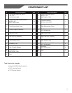
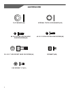
1. Before proceeding, familiarize yourself with the parts of the
Cross-Trainer and make sure that you have received all the
items described in the Component List.
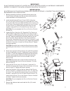
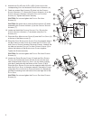
2. Locate the left and right FRONT COVER (9 &10). Using two
PHILLIPS PAN HEAD POINTED SCREWS (3), mount the LEFT FRONT
COVER (9) to the FRAME (A). Attach the RIGHT FRONT COVER (10)
to the FR
AME
in the same manner using two PH
ILLIPS
PA
N
HE
AD
PO
INTED
SC
REWS
(3). Secure the tops of the FR
ONT
CO
VERS
together using two PH
ILLIPS
PA
N
HE
AD
PO
INTED
SC
REWS
(3).
CAUTION: Do not overtighten the PHILLIPS PAN HEAD POINTED
SCREWS (3).
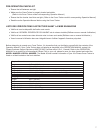
3. Locate the R
IGHT USER ARM (12). Snap the 2-PIN CONNECTOR
(2PA) located at the bottom of the RIGHT USER ARM into the 2-
PIN CONNECTOR (2PB) positioned at the top of the RIGHT ROCKER
ARM (B). Feed the connectors and excess cable up into the
RIGHT USER ARM. Secure the RIGHT USER ARM to the RIGHT
ROCKER ARM using three HEX SOCKET HEAD CAP SCREWS (1) and
three INTERNAL TOOTH LOCK WASHERS (18). Repeat the procedure
for the LEFT USER ARM (11) and LEFT ROCKER ARM (C). Tighten
all screws securely.
CAUTION: Be careful not to pinch the WIRE HARNESSES when
assembling the USER ARMS (11 &12) to the ROCKER ARMS (B &
C).
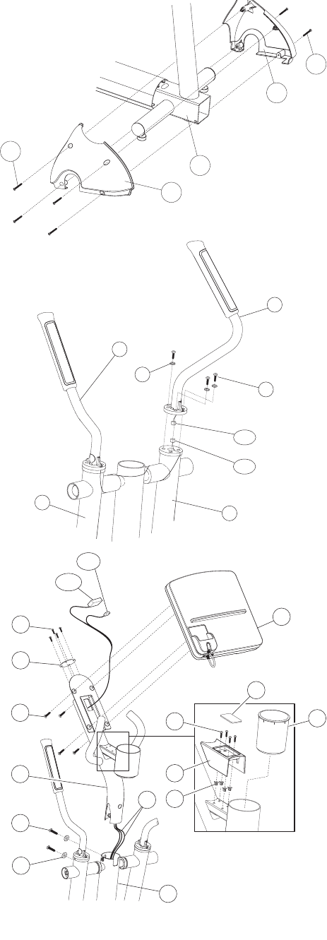
4. Detach and unwrap the WIRE HARNESS (E) (16P, 4P) located at
the top of the MONOCOLUMN (F). Holding the CONSOLE SUPPORT
ASSEMBLY (7) with the handgrips facing upward, feed the WIRE
HARNESS up through the neck and out the top access hole.
Carefully lower the CONSOLE SUPPORT ASSEMBLY into the
MONOCOLUMN.
CAUTION: Be careful not to pinch the WIRE HARNESSES (E)
when assembling the CONSOLE SUPPORT ASSEMBLY (7) to the
MONOCOLUMN (F).
5. Using two HEX SOCKET HEAD CAP SCREWS (1) and two FLAT
WASHERS (8), secure the CONSOLE SUPPORT ASSEMBLY (7) to the
MONOCOLUMN (F). Tighten the SCREWS securely.
6. Insert the GROMMETS (20) into the four holes on the CONSOLE
SUPPORT ASSEMBLY. Locate the ACCESSORY TRAY (17). Align the
A
CCESSORY TRAY with the four holes on the CONSOLE SUPPORT
ASSEMBLY. Using four PHILLIPS PAN HEAD POINTED SCREWS (3),
secure the ACCESSORY TRAY to the CONSOLE SUPPORT ASSEMBLY
as shown. Tighten the SCREWS securely.
CAUTION: Do not overtighten the P
HILLIPS PAN HEAD POINTED
SCREWS (3).
7. Remove the adhesive back and install the P
AD (23). Install
the C
UP (22).
3
10
A
9
3
4P
16P
21
4
3
23
19
2
1
7
F
E
17
20
22
8
11
18
C
B
12
1
2PA
2PB
5