


14
2P
2PL
15
F
13
10
2PR
2P
J
19
8
15
F
8
16
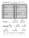
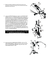
4. (Model 9500HR / 9100) Locate the TELEMETRY CABLE (#17).
Feed the 3-PIN CONNECTOR (3P) end of the cable through the
front of the HANDLEBAR ASSEMBLY (#15). The cable must be
routed down the HANDLEBAR BRACKET TUBE (F) and back up
the top of the MONOCOLUMN (#10). Feed the 3-PIN
CONNECTOR through the DISPLAY CONSOLE MOUNTING
BRACKET (D) ACCESS HOLE.
(Model 9500HR) Locate the HEART RATE CABLE (#18). In
similar fashion, feed the 4-PIN CONNECTOR (4P) end of the cable
through the front of the HANDLEBAR ASSEMBLY (#15). The
cable must be routed down the HANDLEBAR BRACKET TUBE
(F) and back up the top of the MONOCOLUMN (#10). Feed the 4-
PIN CONNECTOR through the DISPLAY CONSOLE MOUNTING
BRACKET (D) ACCESS HOLE. Pull the LEFT HEART RATE
SENSOR CABLE (2PL) (Red/Black) through the LEFT LARGE
HOLE (H) of THE HANDLEBAR BRACKET TUBE. Pull the RIGHT
HEART RATE SENSOR CABLE (2PR) (Green/White) through the
RIGHT LARGE HOLE of THE HANDLEBAR BRACKET TUBE.
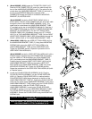
5. (Model 8500 / 9100) Align the USER LEFT BULLHORN (#13) to
the HANDLEBAR BRACKET TUBE (F). Using three MOUNTING
SCREWS (#6), secure the USER LEFT BULLHORN to the
HANDLEBAR BRACKET TUBE and the HANDLEBAR (#15).
Tighten the SCREWS securely. Repeat the procedure for the
USER RIGHT BULLHORN (#14).
(Model 9500HR) Locate the USER LEFT BULLHORN (#13) with a
Lifepulse sensor. Connect the 2-PIN CONNECTOR (2P) leading
from the USER LEFT BULLHORN to the 2-PIN CONNECTOR
(2PL) now leading from the HANDLEBAR BRACKET TUBE (F).
Carefully feed any excess HEART RATE CABLE (#18) into the
HANDLEBAR BRACKET TUBE and secure the USER LEFT
BULLHORN to the HANDLEBAR BRACKET TUBE using three
MOUNTING SCREWS (#6). Tighten the SCREWS securely.
Repeat the procedure for the USER RIGHT BULLHORN (#14) with
a Lifepulse sensor.
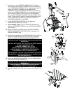
6. Locate the POLAR RECEIVER ASSEMBLY (#16). Plug the
POLAR RECEIVER ASSEMBLY into the POLAR RECEIVER
JACK (J). Place the POLAR RECEIVER in a vertical position,
POLAR RECEIVER JACK facing downward, at the front of the
HANDLEBAR BRACKET TUBE (F). Position the POLAR COVER
(#19) over the center of the HANDLEBAR ASSEMBLY (#15) at the
HANDLEBAR BRACKET TUBE. Making sure the POLAR COVER
is oriented properly, slide the POLAR COVER over the
HANDLEBAR ASSEMBLY covering the POLAR RECEIVER
ASSEMBLY and the end of the HANDLEBAR BRACKET TUBE.
The POLAR COVER should fully nest over the HANDLEBAR
ASSEMBLY. Secure the POLAR COVER using two MOUNTING
SCREWS (#8).
CAUTION: DO NOT OVER-TIGHTEN THE PHILLIPS PAN HEAD
SCREWS (#8).
MISE EN GARDE : NE SERREZ PAS EXCESSIVEMENT LES
VIS CRUCIFORMES À TÊTE CYLINDRIQUE (Nº 8).
10
3P
15
F
D
17