


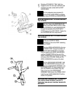
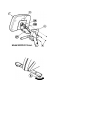
There is a large hole in the rear of the
DISPLAY CONSOLE (#7) through which you
can see a 10-PIN CONNECTOR (10P) or 16-
PIN CONNECTOR (16P), a 3-PIN
CONNECTOR (3P) on a WIRE HARNESS (if
so equipped), and a 4-PIN CONNECTOR (4P)
on a WIRE HARNESS (if so equipped). These
correspond to the matching WIRE HARNESS
CONNECTORS protruding from the top of the
HANDLEBAR ASSEMBLY. Properly align the
LOCKING TABS of the 10-PIN CONNECTOR
or 16-PIN CONNECTOR, 3-PIN
CONNECTOR, and the 4-PIN CONNECTOR
and plug them together until they SNAP into
place.
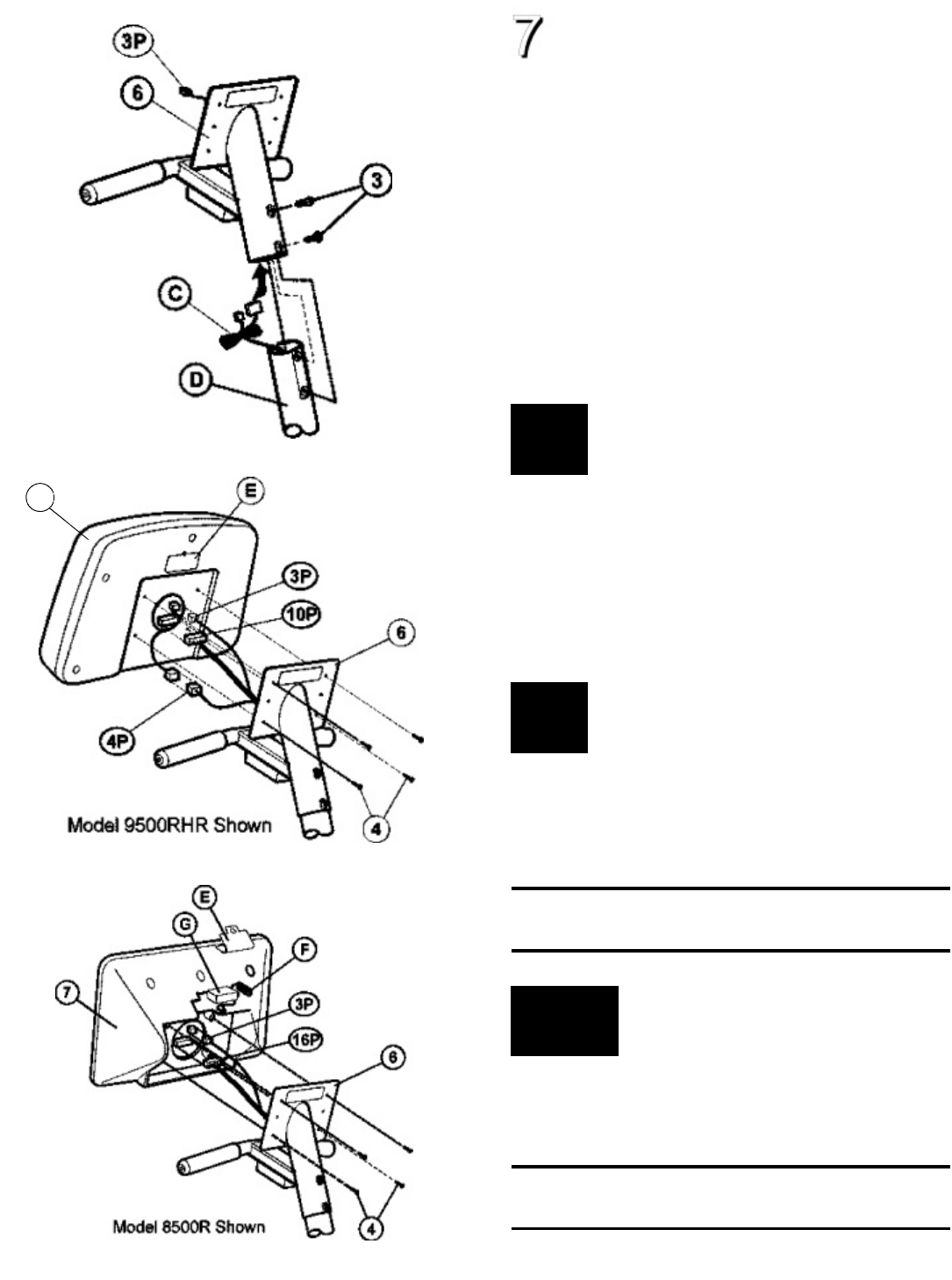
Remove the BATTERY DOOR (E) (if so
equipped) located on the back of the DISPLAY
CONSOLE (#7). Carefully pull the BATTERY
WIRE HARNESS (F) out of the BATTERY
COMPARTMENT. Plug the BATTERY (G) into
the BATTERY WIRE HARNESS
CONNECTOR. Carefully place the BATTERY
and BATTERY WIRE HARNESS into the
BATTERY COMPARTMENT. Replace the
BATTERY DOOR.
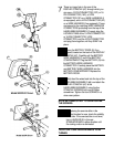
Carefully feed the wires back into the top of the
HANDLEBAR ASSEMBLY (#6) and attach the
DISPLAY CONSOLE (#7) to the
HANDLEBAR ASSEMBLY using the four
CONSOLE SCREWS (#4) and a Phillips
screwdriver. Tighten the four SCREWS in a
criss-cross pattern.
NOTE: BE CAREFUL NOT TO OVERTIGHTEN
THE SCREWS.
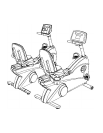
After placing the exercise bike in the
intended location for use, check the stability
of the bike. If the exercise bike is not level,
turn a LEVELER (E) in the rear
STABILIZER BAR in either direction until
the rocking motion is eliminated.
NOTE: ONLY ONE LEVELER NEEDS TO BE
TURNED.
7