


11
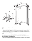
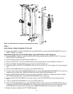
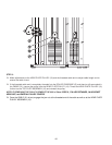
STEP 5
NOTE: INSTALL FROM THE INSIDE OF THE UNIT.
Position two WEIGHT STACK CUSHIONS (20) and GUIDE RODS (16) at the GUIDE ROD BRACKET (G) on the
RIGHT TOWER (11) as shown.
NOTE: MAKE SURE THAT THE PLUGGED END OF THE GUIDE RODS (16) ARE FACING UP.
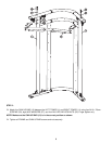
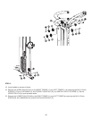
Slide one WEIGHT PLATE (17) over the GUIDE RODS (16) and slowly lower the WEIGHT PLATE (17) onto the
WEIGHT STACK CUSHIONS (20).
Continue stacking a total of fifteen WEIGHT PLATES (17).
Slide one TOP PLATE (18) over the GUIDE RODS (16) and slowly lower it onto the WEIGHT PLATES (17).
Slide one WEIGHT PIN with RING (43) over the stem of the TOP PLATE (18 ).
Thread the HEAD PLATE PULLEY ASSEMBLY (19) into the TOP PLATE (18). Do not tighten! This will be adjusted
later.
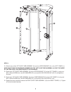
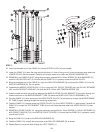
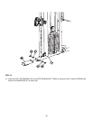
Slide one RETAINING RING (37) over each of the GUIDE RODS (16).
Thread an M10 X 50mm HEX TENSION SCREW (38) into each of two GUIDE ROD RETAINERS (15). Do not fully
thread the M10 X 50mm HEX TENSION SCREW (38) into the GUIDE ROD RETAINERS (15).
Slide the GUIDE ROD RETAINERS (15) into the holes on the RIGHT TOWER (11). Make sure the M10 X 50mm
HEX TENSION SCREW (38) in the GUIDE ROD RETAINERS (15) are facing up.
Push the GUIDE ROD RETAINERS (15) up high enough so that the GUIDE RODS (16) can be placed under
them.
Lower the GUIDE ROD RETAINERS (15) over the GUIDE RODS (16).
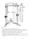
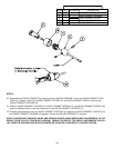
Slide the RETAINING RINGS (37) up. Use a RETAINING RING PLIER to secure the RETAINING RINGS (37) into
the groove on the GUIDE ROD RETAINERS (15). If the groove is hidden inside the hole on the tube, use a 5mm
ALLEN WRENCH to loosen the M10 X 50mm HEX TENSION SCREW (38) until the groove is accessible.
Repeat this step to complete the LEFT TOWER assembly.
NOTE: The Side Shroud is not shown in this illustration for clarity.