


5
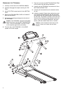
ASSEMBLING THE TREADMILL
Tools Required: Metric Wrench Set, Metric
Allen Wrench Set, Phillips Screwdriver
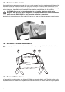
1. Locate the USER LEFT UPRIGHT (A) (upright with
pre-fed CONSOLE CABLE). With the HANDLEBAR
EXTENSION facing the rear of the unit, position the
USER LEFT UPRIGHT near the USER LEFT
UPRIGHT BRACKET (B). Connect the CONNEC-
TORS (C) leading from the USER LEFT UPRIGHT
and USER LEFT UPRIGHT BRACKET. Slide the
USER LEFT UPRIGHT over the USER LEFT
UPRIGHT BRACKET until fully seated. Install one
5/8" BUTTON HEAD SCREW (1) and LOCK WASH-
ER (2) each in the side and rear mounting holes of
the USER LEFT UPRIGHT. Finger-tighten the
SCREWS.
Caution: Do not pinch the cable when sliding the
USER LEFT UPRIGHT (A) over the USER LEFT
UPRIGHT BRACKET (B).
2. Locate the USER LEFT UPRIGHT BRACE (D).
Using four 5/8" BUTTON HEAD SCREWS (1) and
LOCK WASHERS (2), secure the USER LEFT
UPRIGHT BRACE to the front of the USER LEFT
UPRIGHT (A) and the FRAME (E). Finger-tighten
the SCREWS.
3. Locate the USER RIGHT UPRIGHT (F). With the
HANDLEBAR EXTENSION facing the rear of the
unit, position the USER RIGHT UPRIGHT near the
USER RIGHT UPRIGHT BRACKET (G). Slide the
USER RIGHT UPRIGHT over the USER RIGHT
UPRIGHT BRACKET until fully seated. Install one
5/8" BUTTON HEAD SCREW (1) and LOCK WASH-
ER (2) each in the side and rear mounting holes of
the USER RIGHT UPRIGHT. Finger-tighten the
SCREWS.
4. Locate the USER RIGHT UPRIGHT BRACE (H).
Using four 5/8" BUTTON HEAD SCREWS (1) and
LOCK WASHERS (2), secure the USER RIGHT
UPRIGHT BRACE to the front of the USER RIGHT
UPRIGHT (F) and the FRAME (E). Finger-tighten the
SCREWS.
5. Locate the HANDRAIL (J). With the stepped exten-
sion end of the HANDRAIL facing right, position the
HANDRAIL between the LEFT and RIGHT
UPRIGHTS (A) & (F) at the HANDRAIL MOUNTING
HOLES. Secure the user left side of the HANDRAIL
to the LEFT UPRIGHT using the 2" BUTTON HEAD
SCREW (3) and one LOCK WASHER (2). Secure
the user right side of the HANDRAIL to the RIGHT
UPRIGHT using one 5/8" BUTTON HEAD SCREW
(1) and one LOCK WASHER (2).
6. Locate the DISPLAY CONSOLE (K). Position the
DISPLAY CONSOLE near the top ends of the LEFT
and RIGHT UPRIGHTS (A) & (F). Connect the CON-
NECTOR (L) leading from the top of the USER LEFT
UPRIGHT to the CONNECTOR (L) leading from the
user left side of the DISPLAY CONSOLE. Slide the
DISPLAY CONSOLE onto the TOP UPRIGHT
EXTENSIONS. Secure the DISPLAY CONSOLE to
the uprights using two 5/8" BUTTON HEAD
SCREWS (1) and LOCK WASHERS (2) on either
side of the DISPLAY CONSOLE. Tighten the
SCREWS securely.
Caution: Do not pinch the cable when sliding the
DISPLAY CONSOLE (K) onto the LEFT and
RIGHT UPRIGHTS (A) & (F).
7. Tighten all SCREWS securely.
8. Position the TREADMILL into the desired location for
use.
9. Plug the TREADMILL into a proper electrical outlet
as instructed in SECTION 1.2 of this manual.