


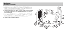
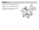

5. Assemble the PULLEY (11), OUTPUT CAM (12) and OUTPUT PLATE (13)
using two M10 X 50mm BOLTS (14), four 3/8" SAE WASHERS (5) and
two M10 NYLOCK NUTS (6) as shown. Tighten the BOLTS and NUTS
securely.
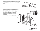
6. Assemble the FRONT SHROUD (15) and REAR SHROUD (16) to the
TOWER (3) using four M10 X 20mm BOLTS (17), four 3/8" SAE WASH-
ERS (5) as shown. Be sure all tabs along the sides and top of the
SHROUDS are fully engaged in the slots located inside the TOWER.
Tighten the BOLTS securely. Do not overtighten the BOLTS.
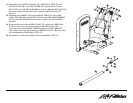
7. Secure the OUTPUT CAM ASSEMBLY (A) to the TOWER
AXLE (B) using one M10 X 25mm BOLTS (18), one 3/8"
SAE WASHERS (5) and one PLATE (19) as shown. Tighten
the BOLT securely.
IMPORTANT: Be sure the OUTPUT CAM ASSEMBLY is ori-
ented as shown before securing it to the TOWER AXLE.