


2
21
72
8
1
G
17
4
1
3
F
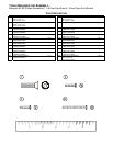
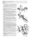
8. Locate the DISPLAY CONSOLE (4). Position the CONSOLE near the
top of the CONSOLE BRACKET. Attach all CONNECTORS leading from
the CONSOLE BRACKET to their corresponding CONNECTORS in the
back of the DISPLAY CONSOLE. Feed any excess WIRE HARNESS
into the CONSOLE BRACKET and place the DISPLAY CONSOLE onto
the CONSOLE BRACKET aligning the mounting holes. Secure the
DISPLAY CONSOLE using four SCREWS (2). Tighten the SCREWS
securely. Do not over-tighten the SCREWS.
9. Locate the CONSOLE SUPPORT COVER (8). Position the CONSOLE
BRACKET COVER over the underside of the CONSOLE SUPPORT
ASSEMBLY (7) as shown and secure it using two SCREWS (2). Tighten
the SCREWS securely. Do not over-tighten the SCREWS.
10. Locate the CONSOLE SUPPORT CAP (21). Snap the CAP into position
at the top of the CONSOLE SUPPORT COVER.
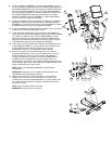
11. Locate the BASE FRAME CAP (19). Remove the two SCREWS (H)
securing the front of the BASE FRAME COVER (J) to the BASE FRAME
(K). Position the CAP over the front of the BASE FRAME as shown
sliding the mounting tabs to the inside of the BASE FRAME COVER.
Secure the CAP using two SCREWS (H) previously removed. Tighten
THE SCREWS securely. Do not over-tighten the SCREWS.
12. Locate the four FOOT COVERS (20). Align the COVERS with the ends
of the STABILIZER BARS (L). Insert the post on the underside of the
FOOT COVERS into the mounting holes on the top of each
STABILIZER. Press the FOOT COVERS firmly into position.
13. With the cross-trainer in the intended location for use, locate the
supplied POWER SUPPLY (#11) and LINE CORD (#12). A coaxial
broadcast supply line with an F-Type connector (not supplied) is
required for entertainment viewing. Connect the POWER SUPPLY
CONNECTOR to the appropriate connector located on the front
underside of the cross-trainer. Connect the broadcast supply line at this
time if available. Connect the LINE CORD to the POWER SUPPLY and
plug the LINE CORD into a power outlet.
NOTE: Refer to the OPERATION MANUAL for specific power
requirements.
REMARQUE : Reportez-vous au GUIDE D'UTILISATION pour les
caractéristiques de l'alimentation électrique.
14. With the cross-trainer in the intended location for use, check the
stability of the cross-trainer. If the cross-trainer is not level, turn a
LEVELER (M) in the front STABILIZER BAR (L) in either direction until
the rocking motion is eliminated. Tighten the JAM NUT (N) when the
cross-trainer is level.
NOTE: Only one leveler needs to be turned.
REMARQUE : Ne tourner qu’un seul vérin.
H
20 N J
K19
LM
1112