


2
21
72
8
1
G
17
4
1
3
F
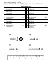
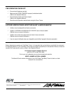
IMPORTANT! Do not discard the ship kit located on top of the pedal levers. All necessary components needed to
complete the installation are located in the ship kit.
IMPORTANT! Ne jetez pas le kit placé sur le dessus des leviers de pédale. Il contient tous les éléments nécessaires
pour l'installation.
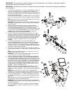
1. Locate the LEFT HANDLEBAR (11). Position the HANDLEBAR near the top of
the LEFT PIVOT ARM (A). Connect the HEART RATE CONNECTOR (B)
leading from the HANDLEBAR to the CONNECTOR (C) extending from the top
of the LEFT PIVOT ARM. Carefully slide the excess HEART RATE CABLE into
the top of the LEFT PIVOT ARM.
Align the mounting holes of the LEFT HANDLEBAR with the mounting holes at
the top of the LEFT PIVOT ARM. Secure them together using three SCREWS
(1).
NOTE: Be careful not to pinch the HEART RATE CABLE when securing the
LEFT HANDLEBAR to the LEFT PIVOT ARM.
REMARQUE : Faites attention de ne pas coincer le CÂBLE DU MONITEUR
DE FRÉQUENCE CARDIAQUE en fixant le GUIDON GAUCHE au BRAS
MOBILE GAUCHE.
2. Locate one LEFT FRONT ROCKER COVER (5) and the LEFT BACK
ROCKER COVER (6). Position the LEFT BACK ROCKER COVER over the
user side of the ROCKER ARM making sure that it seats fully over the
BULLHORN MOUNTING BRACKET (D). Place the FRONT ROCKER COVER
over the opposite side of the ROCKER ARM in the same manner. Secure the
COVERS using two PHILLIPS PAN HEAD SCREWS (2). Tighten the
SCREWS securely. Do not over-tighten the SCREWS.
3. Locate one FRONT PIVOT ARM COVER (9) and one BACK PIVOT ARM
COVER (10). Position the BACK PIVOT ARM COVER over the user side of the
ROCKER ARM making sure that it interlocks with the ROCKER COVER. Place
the FRONT PIVOT ARM COVER over the opposite side of the PIVOT ARM in
the same manner. Secure the COVERS using two PHILLIPS PAN HEAD
SCREWS (2). Tighten the SCREWS securely. Do not over-tighten the
SCREWS.
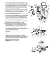
4. Locate the LEFT BULLHORN (13). Secure the BULLHORN to THE
BULLHORN MOUNTING BRACKET (D) using two FLAT HEAD SCREWS (1).
Tighten the SCREWS securely. Locate and attach the LEFT BULLHORN
COVER (15) to the base of the BULLHORN using one SCREW (22). Tighten
the SCREW securely. Do not over-tighten the SCREW. Slide the GASKET (E)
downward to meet the BULLHORN COVER.
5. Repeat steps one through four to install the RIGHT ROCKER COVERS (5 &
6), PIVOT ARM COVERS (9 & 10), BULLHORN (14) and BULLHORN COVER
(16).
NOTE: The right PIVOT ARM COVERS are reversed front and back. The
SCREWS will be installed from the rear.
REMARQUE : Les couvercles du BRAS MOBILE DROIT sont inversés à
l'avant et à l'arrière. Les VIS sont insérées de l'arrière.
6. Unwrap the MAIN WIRE, COAXIAL CABLE and HEART RATE HARNESS
leading from the MONOCOLUMN (F). Feed the WIRE HARNESSES through
the CONSOLE SUPPORT ASSEMBLY TUBE (G) located at the top and front
of the MONOCOLUMN. Locate the CONSOLE SUPPORT ASSEMBLY (7) and
position it near the top of the MONOCOLUMN. Feed the WIRE HARNESSES
through the CONSOLE SUPPORT ASSEMBLY as shown. Align the bottom
mounting holes of the CONSOLE SUPPORT ASSEMBLY with those in the
CONSOLE SUPPORT ASSEMBLY TUBE. Secure them together using six
SCREWS (1). Tighten the SCREWS securely.
NOTE: Be careful not to damage the WIRE HARNESSES when routing it
through the CONSOLE SUPPORT ASSEMBLY or when mounting the
CONSOLE SUPPORT ASSEMBLY to the CONSOLE SUPPORT ASSEMBLY
TUBE.
REMARQUE : Faites attention de ne pas coincer les FAISCEAUX DE
CÂBLES en les insérant dans le SUPPORT DE LA CONSOLE ou en fixant le
SUPPORT DE LA CONSOLE au TUBE DE SUPPORT DE LA CONSOLE.
7. Locate the ACCESSORY TRAY (17). Slide the ACCESSORY TRAY into the
top of the MONOCOLUMN (F) as shown. Be sure the ACCESSORY TRAY is
fully seated.
NOTE: Be careful not to damage the MAIN WIRE HARNESS when sliding
the ACCESSORY TRAY into the MONOCOLUMN.
REMARQUE : Faites attention de ne pas endommager le FAISCEAU DE
CÂBLES PRINCIPAL en glissant le PLATEAU POUR ACCESSOIRES sur la
COLONNE MONOBLOC.
Secure the ACCESSORY TRAY to the CONSOLE SUPPORT ASSEMBLY
using two SCREWS (3). Tighten the SCREWS securely. Do not over-tighten
the SCREWS.
9
11
1
10
2
B
C
A
5
6
2
13
1
15 22
A
D
E