


1.2 Setup
Read the Operation Manual before setting up the Upright Lifecycle
®
Exercise Bike.
Electrical Power Requirements
An optional external power supply is available for the Inclusive Upright Lifecycle Exercise Bike. The external power supply
requires an AC power supply according to the electrical configurations listed in the chart below.
NOTE: Do not modify the plug provided with this product. If the plug does not fit into an available electrical outlet, have a proper
outlet installed by a qualified electrician.
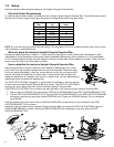
Where to place the Inclusive Upright Lifecycle Exercise Bike
Following all safety instructions in Section 1.1, move the bike to the location in which it will be used. See Section 3, titled
Specifications, for the dimensions of the product footprint (assembled dimensions). Allow a distance of 21 to 30 centimeters
( 8 to 12 inches) between the bike and other objects or surfaces on either side. Allow a distance of 1 meter ( 3 feet ) from the
front or rear of the bike to any other object or surface.
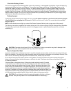
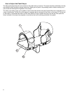
How to stabilize the Inclusive Upright Lifecycle Exercise Bike
After placing the bike in position, check the unit’s stability by attempting to rock it from
side to side. Any slight rocking indicates that the unit must be leveled. Determine which
foot is not resting completely on the floor. Loosen the jam nut (A) with an open-end M17
wrench, and rotate the stabilizing foot (B) to lower it. Verify that the bike is stable, and
repeat the adjustment as necessary until the unit no longer rocks. Lock the adjustment by
tightening the jam nut against the stabilizer bar.
The STEP-UP PLATFORM is shipped in a configuration to be placed on the user left side
of the Inclusive Upright Lifecycle
®
Exercise Bike (as shown). The STEP-UP PLATFORM is
designed for use on either side of the Inclusive Upright Lifecycle
®
Exercise Bike.
If the STEP-UP PLATFORM is to be used on the user right side of the Inclusive Upright Lifecycle
®
Exercise Bike:
1. Remove the four SCREWS (AA) securing the STEP-UP PLATFORM (BB) to the STEP LOCATOR BRACKET (CC).
2. Flip the STEP LOCATOR BRACKET (CC), align the STEP LOCATOR BRACKET to the STEP-UP PLATFORM (BB)
and secure using the four previously removed SCREWS (AA). Tighten the SCREWS securely. Do not overtighten
the SCREWS.
Peel the protective liner from each of the six NON-SLIP PADS (DD) and place them on the underside of the STEP
LOCATOR BRACKET (CC) as shown.
Carefully lift the rear of the Inclusive Upright Lifecycle Exercise Bike and position the STEP-UP PLATFORM under the
REAR STABILIZER (EE) as shown. Be sure the REAR STABILIZER sits completely on the floor within the STEP
LOCATOR BRACKET (CC).
6
Supply Voltage
(VAC)
100
110
120
200
220
230
240
Frequency
(Hz)
50 / 60
50 / 60
50 / 60
50 / 60
50 / 60
50 / 60
50 / 60
Rated Current
(Amps)
1.6
1.6
1.6
.8
.8
.8
.8
A
B