MODELS NEW 95TI TREADMILLS
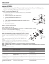
TOOLS REQUIRED: Phillips Screwdriver, Metric Allen Set, M16 & M17 Wrench
PARTS
NOT USED FROM KIT: (1) Main Bracket Cap, (1) Grommet
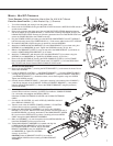
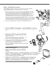
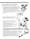
1. Turn off the treadmill and unplug it from the power outlet.
2. Remove the six SCREWS securing the MOTOR COVER. Remove the MOTOR COVER and set it
and the screws aside.
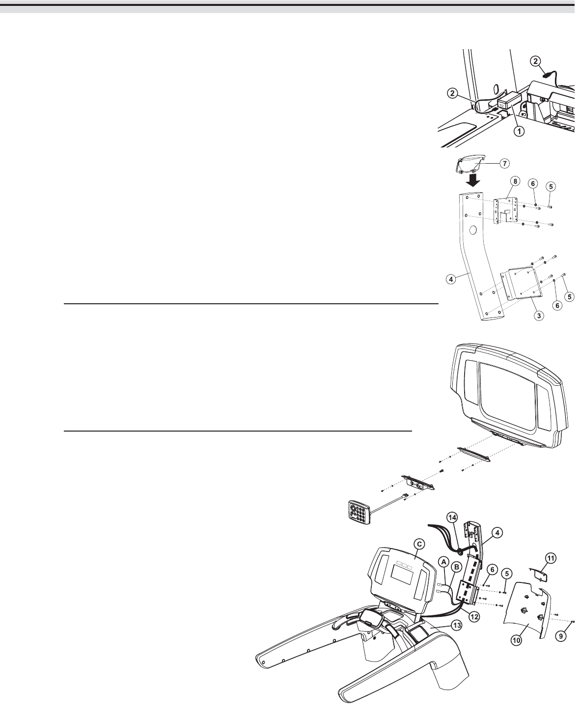
3. Remove the protective liner from one of the provided FASTENER STRIPS. Attach the fastener
strip to the bottom of the POWER BLOCK (1). Interlock the remaining FASTENER STRIP to the
installed FASTENER STRIP. Remove the remaining protective liner from FASTENER STRIP and
secure the POWER BLOCK to the FRAME as shown.
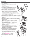
4. Plug the POWER CORDS (2) leading from the MOTOR COMPARTMENT and LEFT UPRIGHT
into their respective ends of the POWER BLOCK (1). Feed excess cable into the LEFT UPRIGHT.
5. Re-install the MOTOR COVER using the six previously removed SCREWS.
6. Attach the LOWER MOUNTING BRACKET (3) to the MAIN BRACKET (4) as shown using four
SCREWS (5) and WASHERS (6) each. Tighten the SCREWS securely. (8-10 ft. lbs.)
7. Slide the new BRACKET COVER (7) over the top end of the MAIN BRACKET (4) and down to
meet the LOWER MOUNTING BRACKET (3) as shown.
8. Attach the TV BRACKET (with bent tab) (8) to the MAIN BRACKET (4) as shown using four
SCREWS (5) and WASHERS (6). Tighten the SCREWS securely. (8-10 ft. lbs.)
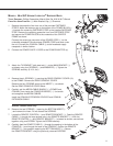
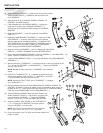
9. Remove the two SCREWS (9) securing the REAR CONSOLE COVER (10) to the FRAME.
Remove the REAR CONSOLE COVER. Remove the TOP INSERT (11) from the REAR CON-
SOLE COVER and discard. Set the REAR CONSOLE COVER aside.
Achieve Console Units Only:
10. Remove the two SCREWS (--) securing the BOTTOM INSERT (--) and remove the insert. Do not
discard the SCREWS.
11. Locate the REMOTE CONTROL (--) and REMOTE BRACKET (--). Feed the REMOTE CABLE (--
) through the large access hole in the REMOTE BRACKET (--). With the REMOTE CONTROL (-
-) and REMOTE BRACKET (--) oriented as shown, secure them together using one SCREW.
Tighten the SCREW securely.
12. Carefully feed the REMOTE CABLE (--) through the opening in the bottom of the CONSOLE (--
) and through the back of the CONSOLE. Position the REMOTE BRACKET (--) into position
replacing the BOTTOM INSERT (--). Secure the REMOTE BRACKET using the previously
removed SCREWS.
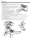
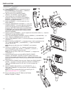
13. Carefully pull the MEDIA CABLE BUNDLE (12) (POWER, COAXIAL, I-R CONTROL
(remote cable on achieve consoles), S-VIDEO) from inside the CONSOLE BRIDGE
(13). Un-bundle and straighten the MEDIA CABLES.
Install the COAXIAL EXTENSION COUPLER and COAXIAL EXTENSION
CABLE.
14. Connect the I-R CONTROL (A) and S-VIDEO (B) CABLES to the back
of the DISPLAY CONSOLE (C).
15. Tape the ends of the all CABLES (POWER, COAXIAL, I-R CONTROL
(remote cable on achieve consoles), S-VIDEO) together.
16. Holding the MAIN BRACKET ASSEMBLY (4) close to the CONSOLE
BRIDGE (13) as shown. With the holes facing upward, feed the taped end of
the MEDIA CABLES (12) through the bottom of the MAIN BRACKET ASSEM-
BLY and out of the UPPER HOLE as shown. Carefully pull excess MEDIA
CABLE through the MAIN BRACKET ASSEMBLY.
17. Slide one GROMMET (14) over the taped end of the MEDIA CABLES (12).
Install the GROMMET into the top access hole.
18. Tilt the MAIN BRACKET ASSEMBLY (4) upward and align the
LOWER MOUNTING BRACKET (3) holes with those in
the CONSOLE BRACKET POSTS. Secure the MAIN
BRACKET ASSEMBLY using four SCREWS (5)
and WASHERS (6). Tighten the SCREWS
securely. (8-10 ft. lbs.)
CAUTION: Raise the BRACKET COVER (7) to meet the
exiting MEDIA CABLES before mounting the MAIN BRACKET
ASSEMBLY.
7


