


812
8.
9.
10.
11.
12.
13.
14.
15.
16.
17.
18.
19.
20.
21.
22.
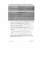
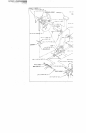
INNER/OUTER THIGH MACHINE. ASSEMBLY INSTRUCTIONS
Insert two (2) 2 IN. SQ. END CAPS into both ends of the BEARING HOUSING as shown on drawing.
SECURELY assemble the BEARING HOUSING to the BASE using two (2) 3/8 X 3 IN BOLTS, four
(4) 3/8 IN WASHERS, and two (2) 3/8 IN. LOCK NUTS.
Insert two (2) 2 IN. SQ. END CAPS into both ends of the PULLEY MOUNT as shown on &rowing.
SECURELY assemble the the PULLEY MOUNT to the BASE as shown on drawing, using two (2) 318
X 3 IN. BOLTS, four (4) 3/8 IN. WASHERS, and two (2) 3/8 IN. LOCK NUTS. (MAKE SURE
PULLEY MOUNT IS ATTAClqT~D AS IT IS SHOWN IN THE DRAWING)
SECURELY assemble two (2) SPRING PIN ASSEMBLIES to the ARMS as shown in CI)E~AIL A).
Insert four (4) 3/4 IN. FLANGE BEARINGS into the BUSHINGS of the ARMS.
Insert the shaft of each SWIVEL ARM through the 3/4 IN. FLANGE BEARINGS on the ARMS as
shown on drawing, and SECURE in place with two (2) 3/4 IN. STAR_LOCK COLLARS.
Insert two (2) 2 IN. SQ. END CAPS into the ends of the ARMS, as shown on drawing.
Insert four (4) 3/4 IN. FLANGE BEARINGS into the BUSHINGS of the BEARING HOUSI~G.
Assemble the ARMS to the BEARING HOUSING, using the following steps:
Carefully tip the BASE on its side.
Slide one (1) 3/4 IN. THRUST WASHER and one (1) ROTARY PLATE onto the shaft of each
Attach each ARM to the BEARING HOUSING and SECURE in place with two (2) 3/4 ~q. STAR
LOCK COLLARS.
SECURELY attach the LEFT and RIGHT tIANDLES to the BASE using two (2) 3/8 x 3-1/~: IN.
BOLTS, four (4) 3/8 IN. WASHERS, and two (2) 3/8 IN. LOCKNUTS.
Slide two (2) 1 X 5 IN. GRI~S over the LEFT and RIGHT HANDLES. (IF A LUBRICAN~I
REQUIRED, COAT ~ INSIDE OF THE GRI~ WITH RUBBING ALCOHOL)
SECURE the SEAT PAD to the LEFT and RIGHT HANDLES using two (2) 3/8 X 1-1/4IN. BOLTS,
two (2) 3/8 IN, LOCK WASHERS, and two (2) 3/8 IN. WASHERS.
SECURE the BACK PAD to the CARRIAGE UPRIGHT using two (2) 3/8 X 2-3/4 IN. BOLTS, two
(2) 3/8 IN. LOCK WASHERS, and two (2) 3/8 IN. WASHERS.
SECURELY attach four (4) 3-1/2 X 1 IN. PULLEYS to the PULLEY MOUNT, as shown on ~kawing,
using two (2) 3/8 X 2 IN. BOLTS, two (2) 3/8 X 3-3/4 IN. BOLTS eight (8) 3/8 IN. WASHEP~’., and
(4) 3/8 IN. LOCK NUTS.
PART #6656601 5
REVISION 10/21/96