


NOTE:
NOTE:
I0.
II.
12.
13.
IF THE REAR SHROUD IS ASSEMBLED TO THE PARS, BODY 425, IT WILL NEED TO BE REMOVED r~r
0
ASSEMBLE THE LEG PRESS AND THE ADAPTER KIT. PLEASE REMOVE THE SHROUD AT THIS TIME
BY REMOVING THE FOUR (4) 3/8 X 1 IN. BOLTS AND FOUR 3/8 IN. WASHERS.
THE LEG PRESS ATTACHMENT (832101) MUST BE ASSEMBLED BEFORE ASSEMBLING IT TO THE
PARABODY 425. PLEASE ASSEMBLE THE LEG PRESS ATTACHMENT AT TIIIS TfME USING THE 832
PRODUCT ASSEMBLY INSTRUCTIONS.
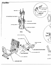
Attach two (2) 2 SQ. IN. COVER CAPS onto the FRONT LEG WELDMENT as shown on drawing.
Remove two (2) I/2 IN. LOCK NUTS and lwo (2) I/2 IN. WASHERS FROM the PRESS BASE \ BASE connection of the
425.
SECURELY assemble the BASE CONNECTION WELDMENT to the PRESS BASE and BASE connection of the 425
using the two (2) I/2 IN. LOCK NUTS REMOVED IN STEP
SECURELY attach the assembled 532 LEG PRESS ATTACHMENT to the FRONT LEG ~rELDMENT using two
I/2 X 3 IN. BOLTS, two (2) 112 IN. WASHERS (~:ROMSTEP 2) and two (2) I/2 IN’. LOCK NLrI’S.
SECURELY attach the 832 to the 425 by connecting the FRONT LEG WELDMENT to the BASE CONNECTION
WELDMENT, using two (2) I/’2 X 3. IN. BOI.TS, two (2) I12 IN. WASHERS and two (2) I12 IN. LOCK NUTS.
Remove one (I) I/4 IN. CAP NUT from the rear L-hook of the TOP BOOM. (LEAVE 2 IN. PULLEY ON L-HOOK)
Assemble one (i) 2 IN. PULLEY to the rear L-hook and secure place ~vith one (I) I/4 IN. CAP
CAREFULLY remove one (I) 3/8 FN. LOCK NLrF and one (1) SWIVEL WITH lVlZILTI-PRESS SHOCK CORD from
rear flat of the BASE.
Remove one 3/8 IN. NUT, one (I) 2-3/8 IN. CABLE RETAJNI’NG CLIP, one (1) 3-1/2 X I IN. PULLEY, one (1) 3/8
I/2 IN BOLT, and one (I) 3/8 I’N. WASHER from the rear flat of the BASE.
Reassemble one (1) 3-1/2 x 1 IN. PULLE~; one (1) 2-3/8 IN. CABLE RETAINING CLIP, one 3/8 IN. WASHER, and one
(1) 3/8 IN. Nlrf, from Step P to the rear flat of the BASE using one (1) 3/8 x 4-1/2 IN. THREADED STUD, and one (1)
318 IN. NUT.
Reassemble one (I) SWIVEL WITH MULTI-PRESS SHOCK CORD to the 3/8 X 4-I/2 IN. THREADED STUD, using one
(I) 318 IN. LOCK NLrT. (PARTS ARE FROM STF.P 8)
Assemble one (1) 3-I/2 x I IN. PULLEY to the flat facing the leg press on the BASE, and one (1) 3-I/2 IN. PULLEY to the
flat on the FRONT LEG WELDMENT using two (2) 3/8 x 2 IN. BOLTS, two (2) 3/8 IN. WASHERS, two (2) 2-3/8
CABLE RETAINING CLIPS, and two (2) 3/8 IN. LOCK NUTS.
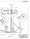
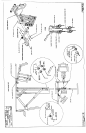
To assemble the LEG PRESS CABLE, follow the cable muting diagram and use lhe follow/ng steps:
Adjust the LEG PRESS so the .¢eat is in its tightest pre-stretch position.
SECURELY attach the loop er, d of the LEG PRESS CABLE to the FRONT LEG WELDMENT using one (I)
QUICK DISCONNECT LINK.
~un the cable through the hole in the D-RING as shown in (DETAIL A) and attach one (I) KEYHOLE CLEVIS
to the end of the LEG PRESS CABLE.
2
12/21/95