Assembly
7
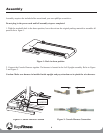
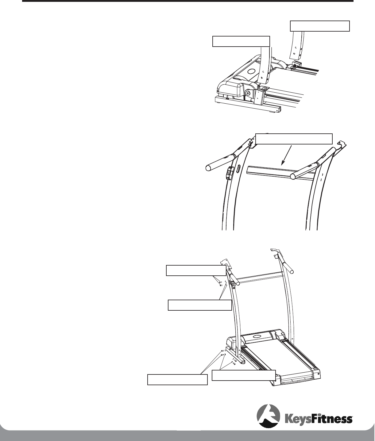
Figure 4: Left and Right Upright Installation
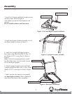
Figure 5: Upright Crossbar Assembly
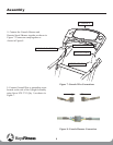
Figure 6: Hardware Installation
3. Install Left Upright and Right Upright to tread-
mill base frame. Refer to Figure 4.
Note: Make sure that the Wire Harness is not
pinched.
Do not install hardware until instructed.
4. Install the Upright Crossbar Assembly to Left
and Right Upright as shown in Figure 5.
5. Attach Left Upright and Right Upright to
base frame using Allen Bolts M8*15 (Qty. 12)
and Washer 9*22*1.6 mm (Qty.12). Refer to
Figure 6.
Note: Lift deck to upright position to install
the Allen Bolts (Qty. 4) on the inside location
of Left and Right Uprights.
6. Attach Upright Crossbar to Left and Right
Uprights using Allen Bolts M8*15 (Qty. 4) and
Washer 9*22*1.6 mm (Qty.4). Refer to Figure
6.
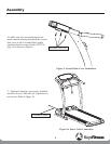
7. Make sure the wire harness is not pinched
and hand tighten all bolts. Wait to tighten all
bolts firmly until unit is fully assembled.
LEFT UPRIGHT
UPRIGHT CROSSBAR
ALLEN BOLT M8*15
ALLEN BOLT M8*15
WASHER 9*22*1.6 mm
WASHER 9*22*1.6 mm
RIGHT UPRIGHT


