8
Assembly
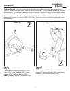
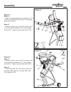
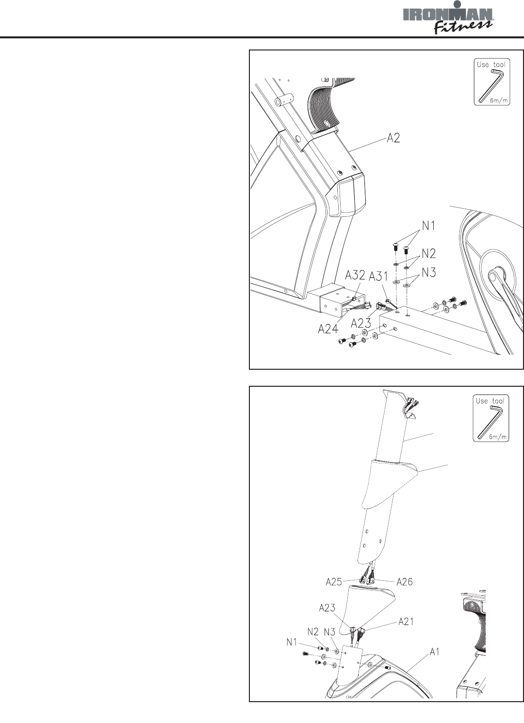
Figure 3
Step 1:
Connect hand pulse sensor wire-rear (A24)
to the hand pulse sensor wire-middle (A23).
Connect the power cord (A31) to power
cord (A32).
Step 2:
Locate the front (A1) and rear (A2) main
frames. Connect both front and rear
frames. To secure, use six bolts (N1), six
spring washers (N2) and six washers (N3) -
make sure all holes are lined up correctly.
Note: Ensure that all wires are secure
inside tube during the entire time both
frames are being secured. Be careful not to
pinch wires.
Figure 3
D
I
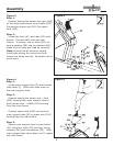
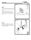
Figure 4
Step 1:
Locate main support tube (D) and console
tube cover (I). Slide main tube cover up
the main support tube.
Step 2:
Connect hand pulse sensor wire - front
(A25) coming from main support tube to
hand sensor wire - middle (A23) coming
from the main frame.
Connect power wire (A26) coming from
main support tube (D) to power wire (A21)
coming from the main frame.
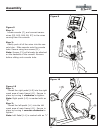
Step 3:
Secure main support tube to main frame
(A1) using four bolts (N1) and four spring
washers (N2) and two washers (N3). Slide
main support tube cover down until it meets
the main frame.
Figure 4


