


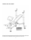
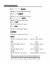
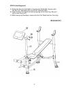
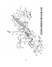
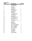

ASSEMBLY INSTRUCTION
Tools Required for Assembling the Machine: Two Adjustable Wrenches and Allen
Wrenches
NOTE: It is strongly recommended that two or more people assemble this machine
to avoid possible injury.
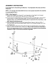
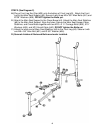
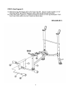
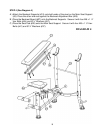
STEP 1 (See Diagram 1)
A.) Plug the two Upright End Caps (#17) onto the bottom of the Right & Left Upright
Beams (#1 & #2). Secure each Cap with a ST5 Screw (#39).
B.) Connect the two Upright Beams by a Cross Brace (#4) in the Mid-span. Secure them
with two M10 x 3 1/8” Carriage Bolts (#29), one Curved Bracket (#12), two ∅ ¾”
Washers (#35), and two M10 Aircraft Nuts (#40) on each end of the Cross Brace. DO
NOT tighten the bolts and nuts.
C.) Attach a Weight Post (#8) to the Right Upright Beam. Secure it with one M10 x 1”
Allen Bolt (#33) and Curved Washer (#38). Slide a 2 3/8” Rubber Bumper (#14) onto
the Weight Post.
D.) Insert the Backrest Adjustment Bar (#19) through the selected holes on the Upright
Beams to obtain desired incline of Backrest. Ensure that the Backrest Adjustment
Bar can be easily removed and re-inserted before you tighten the nuts and bolts
installed in STEP 1-B to achieve maximum alignment.
5