


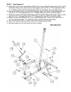
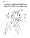
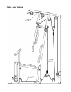
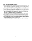
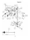
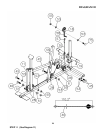
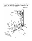
STEP 10 (See Cable Loop Diagram & Diagram 10)
A.) Insert the 110.2” Lower Cable (#30) through the opening on bottom of the Leg
Developer (#11). Attach a Pulley (#28) to the opening. Secure it with one M10 x
2 3/8” Allen Bolt (#46), two ∅ 7/8” Pulley Bushings (#51), and one M10 Aircraft
Nut (#55).
B.) Draw the Cable underneath the Pulley and through the opening on the bottom of
the Main Seat Support to the open bracket on the Main Base Frame (#6).
C.) Attach a Pulley to the bracket. Secure it with one M10 x 1 ¾” Allen Bolt (#45),
two ∅ ¾” Washers (#53), and one M10 Aircraft Nut (#55).
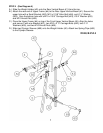
D.) Pull the Cable towards the back of the machine through the bottom opening on
the Front Lower Vertical Beam (#82) to the open bracket on the Main Base
Frame (#6). Repeat the Procedure C to install a Pulley.
E.) Draw the Cable underneath the Pulley then upward to the Double Floating Pulley
Bracket (#19) previously installed. Repeat the Procedure C to install a Pulley to
the open bracket.
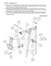
F.) Draw the Cable around the Pulley then downward to the last open bracket on the
Main Base Frame. Repeat the Procedure C to install a Pulley.
G.) Draw the Cable underneath the Pulley then pull upward to the Single Floating
Pulley Bracket (#18) previously installed. Connect the Cable to the Short Chain
(#58) with a C-clip (#57). Then connect the Chain to the Bracket with a M10 x 1”
Allen Bolt (#75), two ∅3/4” Washers (#53) and one M10 Aircraft Nut (#55).
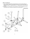
H.) Adjust the length of the Short Chain to adjust the tension of the Cables. If there
is too much sag in the cables, shorten the Chain.
15