


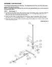
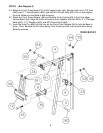
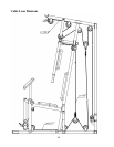
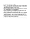
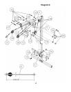
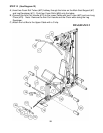
STEP 8 (See Cable Loop Diagram & Diagram 8)
A.) Attach the 129.9” Upper Cable (#31) to the open bracket in the front of Upper Frame (#4).
Attach a Pulley (#28) to the open bracket. Secure it with one M10 x 1 ¾” Allen Bolt (#45),
two ∅ ¾” Washers (#53), and one M10 Aircraft Nut (#55). Note: The Ball Stopper on the
Cable must be underneath the Frame and above the Pulley.
B.) Draw the Cable over the Pulley along the Upper Frame towards the back of the machine.
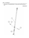
C.) Attach a Pulley (#28) to the open bracket. Secure it with one M10 x 1 ¾” Allen Bolt (#45),
two ∅ ¾” Washers (#53), and one M10 Aircraft Nut (#55).
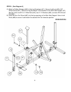
D.) Draw the Cable around the Pulley then downward to the open slot on the Front Press
Base (#12). Attach a Pulley to the open slot. Secure it with one M10 x 5 1/8” Allen Bolt
(#47), two ∅ ¾” Washers (#53), and one M10 Aircraft Nut (#55).
E.) Draw the Cable around the Pulley then upward through the open slot on the Front Upper
Vertical Frame (#5) to an open bracket. Repeat Procedure C above to install a Pulley.
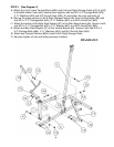
F.) Draw the Cable around the Pulley then pull downward. Attach the Cable to the Single
Floating Pulley Bracket (#18). Repeat the Procedure C to install another Pulley. Let the
Bracket hanging for now.
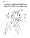
G.) Draw the Cable around the Pulley then pull upward to the last open bracket on the back of
the Upper Frame. Repeat Procedure C to install a Pulley.
H.) Pull the Cable downward to the Weight Holder (#2). Secure the Cable to the Holder with
one M10 x 1” Allen Bolt (#75), two ∅ ¾” Washers (#53), and one M10 Aircraft Nut (#55).
12