


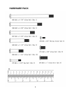
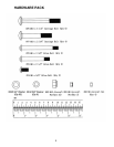
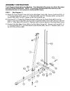
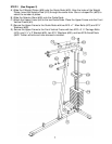
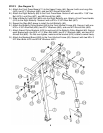
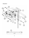
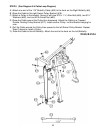
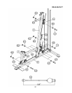
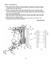
STEP 7 (See Diagram 7 & Cable Loop Diagram)
A.) Attach the 128” Lower Cable (#32) to the open bracket on the bottom of the Leg
Developer (#7).
B.) Attach a Pulley to the bracket. Secure it with one M10 x 1 ¾” Allen Bolt (#69), two Ø
¾” Washers (#80), and one M10 Aircraft Nut (#82).
C.) Draw the Cable underneath the Pulley to the open bracket on the Main Base Frame
(#8). Repeat Step B above to install a Pulley.
D.) Draw the Cable underneath the Pulley along the top of the Main Base Frame through
the hole on the bottom of the Front Vertical Frame to an open bracket. Install
another Pulley.
E.) Pull the Cable upward to the Crossed Double Floating Pulley Bracket (#17)
previously installed in Step-6. Install another Pulley.
F.) Draw the Cable around the Pulley then downward to the open bracket on the Main
Base Frame. Install another Pulley.
G.) Pull the Cable around the Pulley then upward to the Double Floating Pulley Bracket
(#16) previously installed in Step-5. Install another Pulley.
H.) Draw the Cable around the Pulley then pull downward. Connect the Cable to a C-clip
(#50) then connect the C-clip to a Short Chain (#46).
I.) Connect the Short Chain to the bracket on the back of the Front Vertical Frame.
Secure it with one M10 x 1” Allen Bolt (#70), two Ø ¾” Washers (#80), and one M10
Aircraft Nut (#82).
J.) Adjust the tension of the Cable by adjusting the length of the Short Chain. For best
performance of the machine, adjust the Chain so the Selector Stem (Top Plate) on
the weight stack is ¼” above the first plate. While adjusting the weight stack, push
down on the Selector Stem to close up the gap then pin the plates. This will remove
the slag in the cable system so the range of motion is smooth and tight.
14