


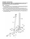
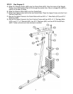
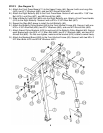
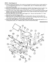
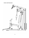
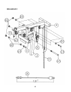
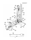
STEP 5 (See Diagram 5 & Cable Loop Diagram)
A.) Attach the 131” Upper Cable (#31) to the opening at the front of the Upper
Frame (#4). Note: The Ball Stopper on the cable should be underneath the
Frame.
B.) Attach a Pulley (#60) to the open bracket. Secure it with one M10 x 1 ¾” Allen
Bolt (#69), two Ø ¾” Washers (#80), and one M10 Aircraft Nut (#82).
C.) Draw the Cable towards the back of the machine to the open bracket on the
Upper Frame. Repeat step B above to install a Pulley.
D.) Draw the Cable around the Pulley then pull back towards the opening on the
Front Press Base (#11).
E.) Attach a Pulley to the opening on the Front Press Base. Secure the Pulley with
one M10 x 6 7/8” Allen Bolt (#65) and one M10 Aircraft Nut (#82).
F.) Draw the Cable around the Pulley and through the opening to the open bracket
on the Front Vertical Beam (#3). Repeat step B above to install another Pulley.
G.) Draw the Cable around the Pulley then pull the Cable downwards. Attach the
Cable to a Double Floating Pulley Bracket (#16). Install another Pulley. Let the
bracket hanging for now.
H.) Pull the Cable upward to the open bracket on the back of Upper Frame. Install
two pulleys to the bracket.
I.) Pull the Cable downward between the two Guide Rods to the Selector Rod
(#13). Thread the bolt at the end of the Cable into the opening on top of the
Selector Rod (#13) to secure the Cable.
11