


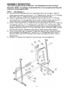
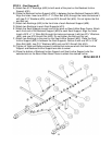
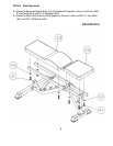
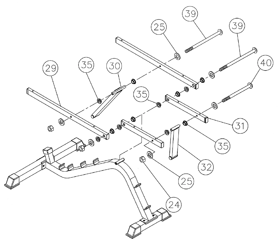
STEP 5 (See Diagram 5)
A.) Attach two Ø ½” Bushings (#35) to both ends of the pivot on the Backrest Incline
Support (#30).
B.) Place the Backrest Incline Support (#30) in between the two Backrest Supports (#29).
Align the holes. Insert one M10 x 7 ¼” Allen Bolt (#39) through the holes and secure it
with two Ø ¾” Washers (#25), and one M10 Aircraft Nut (#24). Do not tighten the Nut
and Bolt yet.
C.) Attach two Bushings (#35) to the front hole of each Backrest Support (#29).
D.) Attach two Bushings to each Seat Supports (#31).
E.) Attach the Seat Supports to each end of the pivot on Bench Main Base Frame. Attach
each front end of the Backrest Support (#29) to each Seat Support. Align the holes.
Insert a M10 x 7 ¼” Allen Bolt through the holes and secure it with two Ø ¾” Washers
(#25), and one M10 Aircraft Nut (#24). Do not tighten the Bolt and Nut yet.
F.) Attach two Bushings to the pivot on the Seat Incline Support (#32). Place the Seat
Incline Support (#32) in between the Seat Supports. Secure it with one M10 x 5 3/8”
Allen Bolt (#40), two Ø ¾” Washers (#25) and one M10 Aircraft Nut (#24).
G.) Tighten all Nuts and Bolts previously installed but make sure both the Seat Incline
Support and Backrest Incline Support are able to swivel.
H.) Place the bottom of Backrest Incline Support and Seat Incline Support onto the
selected slot on the Bench Main Base Frame to obtain the desired incline.
DIAGRAM 5
8