


ASSEMBLY INSTRUCTION
Tools Required Assembling the Machine: Two Adjustable Wrenches and Allen
Wrenches. NOTE: It is strongly recommended two or more people assembling this
machine to avoid possible injury.
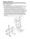
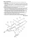
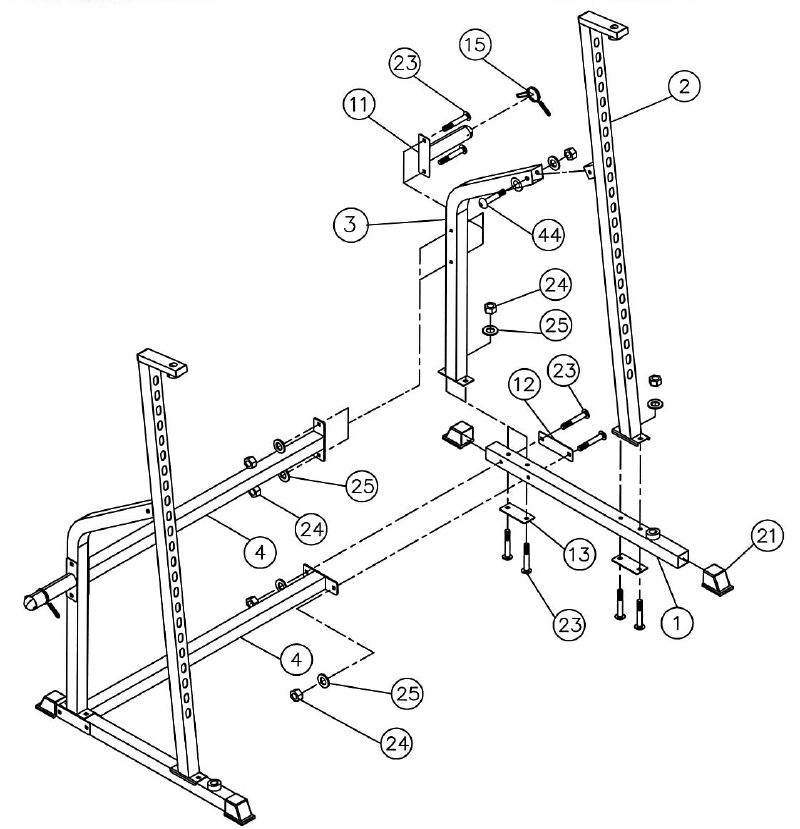
STEP 1 (See Diagram 1)
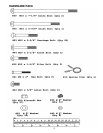
A.) Connect the two Stabilizers (#1) by a Cross Brace (#4) in the mid-span. Align the
holes and secure each end with one 6 ½” x 2” Bracket (#12), two M10 x 2 ¾” Carriage
Bolts (#23), two ∅ ¾” Washers (#25), and two M10 Aircraft Nuts (#24).
B.) Place an Upright Beam (#2) onto a Stabilizer. Secure it with one 4 ¾” x 2” Bracket
(#13), two M10 x 2 ¾” Carriage Bolts (#23), two Ø ¾” Washers (#25), and two M10
Aircraft Nuts (#24). Repeat the same step to install the other Upright Beam.
C.) Attach a Rear Support (#3) to a Stabilizer and an Upright Beam. Secure the Support to
the Stabilizer with one 4 ¾” x 2” Bracket (#13), two M10 x 2 ¾” Carriage Bolts (#23),
two Ø ¾” Washers (#25), and two M10 Aircraft Nuts (#24). Secure the Support to the
Upright Beam with one M10 x 2 ½” Allen Bolt (#44), two Ø ¾” Washers (#25), and one
M10 Aircraft Nut (#24). Repeat the same step to install the other Rear Support.
D.) Place a Cross Brace (#4) in between the two Rear Supports (#3). Secure each end
with one Weight Post Bracket (#11), two M10 x 2 ¾” Carriage Bolts (#23), two Ø ¾”
Washers (#25), and two M10 Aircrafts (#24). Attach one Spring Clip (#15) to each
Weight Post.
E.) Plug four 2” Stabilizer End Caps (#21) onto the end of the two Stabilizers.
4