


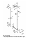
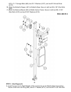
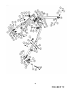
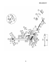
A.) Attach the two Cross-over Swivel Pulley Brackets (#10) to left and right Upper Side Frame
(#7). Secure each Bracket with four M8 x 3/8” Allen Bolts (#101) and four Ø 5/8” Washers
(#106).
B.) Remove the U-shaped Connector, Big Washer, and Ball Stopper from one end of 266”
Upper Cable (#47).
C.) Attach a Pulley (#62) to the left Swivel Bracket and secure it with one M10 x 1 ¾” Allen Bolt
(#93), two Ø ¾” Washers (#107), and one M10 Aircraft Nut (#110).
D.) Insert the end of Cable through the left Cross-over Swivel Pulley Bracket (#10). Draw the
Cable over the Pulley and pull it towards the back of the machine.
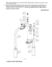
E.) Attach a Cable Roller (#42) to the left Cross-over Swivel Pulley Bracket (#10). Secure it with
one M8 x 1 5/8” Allen Bolt (#102), two Ø 5/8” Washers (#106), and one M8 Aircraft Nut
(#109).
F.) Attach a Small Pulley (#63) to the opening on the left Upper Side Frame. Secure it with one
M10 x 2 ¾” Allen Bolt (#97), two Ø ¾” Washers (#107), and one M10 Aircraft Nut (#110).
Draw the Cable around the top of the Small Pulley.
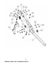
G.) Attach another Small Pulley (#63) to the opening next to the Small Pulley installed in F.
Repeat F to install the Small Pulley. Draw the Cable under the Small Pulley to an open
pulley shaft.
H.) Attach a Pulley (#62) to the open pulley shaft. Secure it with one M10 x 1 ¾” Allen Bolt
(#93), one Ø ¾” Washer (#107), and one Cable Retainer (#78).
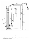
I.) Draw the Cable around the Pulley then to an open pulley shaft on Rear Upper Frame (#18).
Attach a Pulley to the open shaft. Secure it with one M10 x 2 ¾” Allen Bolt (#97), two Ø ¾”
Washers (#107), one Cable Retainer (#78), and one M10 Aircraft Nut (#110).
J.) Draw the Cable around the Pulley and to the open bracket on the Rear Upper Frame (#18).
Attach a Pulley to the bracket. Secure it with one M10 x 5” Allen Bolt (#99), one Cable
Retainer (#78), two Ø ¾” Washers (#107), and one M10 Aircraft Nut (#110).
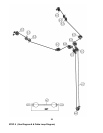
K.) Draw the Cable around the Pulley and downward. Attach a Pulley to a Single Floating Pulley
Bracket (#34). Secure the Pulley with one M10 x 2” Allen Bolt (#94), two Ø ¾” Washers
(#107), two Cable Retainers (#78), and one M10 Aircraft Nut (#11). Draw the Cable upward
to the open bracket one the other side on Rear Upper Frame (#18). Let the Pulley hanging
for now.
L.) Remove the Nut and Washer installed in J. Attach a Pulley onto the Allen Bolt (#99), then
attach a Cable Retainer (#78) to the Pulley, and secure with the removed Washer and Nut.
M.) Draw the Cable to open shaft on Rear Upper Frame. Repeat I to install a Pulley.
N.) Draw the Cable to an open pulley shaft. Repeat H to install a Pulley.
O.) Draw the Cable to the opening on the right Upper Side Frame. Repeat F to install two Small
Pulleys #63).
P.) Draw the Cable through the right Cross-over Swivel Pulley Bracket. Repeat E to install a
Cable Roller (#42).
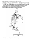
Q.) Re-install the Ball Stopper; Big Washer, and the U-shaped Connector previously removed in
A above. Connect a Single Handle (#79) to each end of the Cable with a Hook (#73). Secure
each Hook with one M10 x 1 1/8” Allen Bolt (#92) and M10 Aircraft Nut (#110).
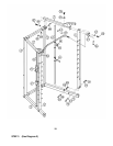
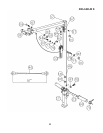
17
DIAGRAM 7-1