


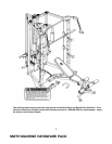
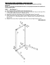
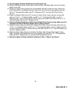
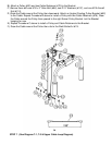
A.) Do not tighten all Nuts and Bolts until instructed to so.
B.) Attach the Middle Vertical Frame (#9) under the Rear Top Beam (#6) and onto the Rear
Base Frame (#8).
C.) Attach the Lower Pulley Frame (#16) to the Middle Vertical Frame from rear. Attach the
Foot Plate (#32) to the Middle Vertical Frame from front. Secure them together with two
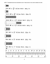
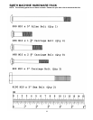
M10 x 3” Carriage Bolts (#89), two Ø ¾” Washers (#107), and two M10 Aircraft Nuts
(#110).
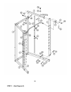
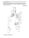
D.) Attach the Weight Glide Post (#17) to rear of Lower Pulley Frame. Secure the top hole
with one 3 1/8” x 1 ¾” Bracket (#36), one M10 x 2 ½” Carriage Bolt (#88), one Ø ¾”
Washer (#107), one M10 Aircraft Nut (#110). Secure the lower hole with one M10 x 2 ½”
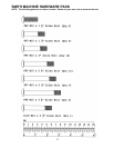
Allen Bolt (#95) and one Ø ¾” Washer (#107).
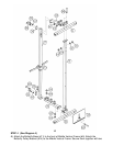
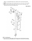
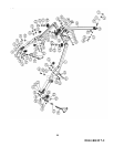
E.) Slide the Sliding Weight Post (#23) to the Weight Glide Post from top. Make sure the
triangular bracket on Sliding Weight Post is facing upward.
F.) Attach the Rear Upper Frame (#18) to Weight Glide Post. Secure the lower hole with one
3 1/8” x 1 ¾” Bracket (#36), one M10 x 2 ½” Carriage Bolt (#88), one Ø ¾” Washer (#107),
one M10 Aircraft Nut (#110). Secure the top hole with one M10 x 2 ½” Allen Bolt (#95) and
one Ø ¾” Washer (#107).
G.) Attach the Rear Upper Frame to the Rear Top Beam (#6). Secure Rear Upper Frame,
Rear Top Beam, and Middle Vertical Frame together with two M10 x 2 ½” Carriage Bolts
(#88), two Ø ¾” Washers (#107), and two M10 Aircraft Nuts (#110).
H.) Securely tighten all Nuts and Bolts installed in Step-1, Step-2, and Step-3.
11
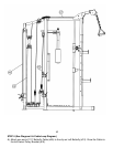
DIAGRAM 3