


ASSEMBLY INSTRUCTION
Tools Required Assembling the Machine: Two Adjustable Wrenches and Allen
Wrenches. NOTE: It is strongly recommended this machine to be assembled by two
or more people to avoid possible injury.
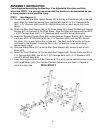
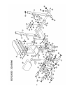
STEP 1 (See Diagram 1)
A.) Connect the Left and Right Upright Beams (#3) & (#4) by a Cross Brace (#5) in the mid-
span. Align the holes then secure them together with two M10 x 2 ¾” Carriage Bolts
(#41), ∅ ¾” Washers (#42) and M10 x Aircraft Nuts (#44) on each end of the Cross
Brace.
B.) Attach the Main Seat Support (#2) to the Cross Brace (#5). Attach the Backrest Support
Bracket (#21) to the back of the Cross Brace. Align the holes and secure with two M10
x 3 1/8” Carriage Bolts (#40), ∅ ¾” Washers (#42), and M10 Aircraft Nuts (#44).
C.) Attach the Backrest Support Post (#20) to the Backrest Support Bracket (#21). Secure
it with one M10 x 3” Allen Bolt (#36), two ∅ ¾” Washers (#42), and one M10 Aircraft
Nut (#44). Do not over tighten the nut and bolt. The Post needs to be able to flip up
and down on the Bracket. Leave the Post in the “up” position except when doing
decline bench press.
D.) Slide the Sliding Block (#11) onto the Main Seat Support (#2). Secure it with a Lock
Knob (#53).
E.) Attach the Front Stabilizer (#1) to the Main Seat Support (#2). Secure it with one M10 x
2 ½” Carriage Bolt (#56), two M10 x 3 1/8” Carriage Bolts (#40), ∅ ¾” Washers (#42),
and M10 Aircraft Nuts (#44).
F.) Insert the Long and Short Left Bar Catches (#13) & (#15) into the selected holes on the
Left Upright Beam (#3). Turn the Bar Catches clockwise to lock them in. Repeat to
install the other side.
DIAGRAM 1
4