


ASSEMBLY INSTRUCTION
Tools Required Assembling the Machine: Two Adjustable Wrenches and Allen
Wrenches
NOTE: It is strongly recommended two or more people assembling this machine to
avoid possible injury.
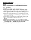
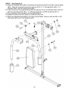
STEP 1 (See Diagram 1)
A.) NOTE: Do not tighten the Nuts and Bolts until instructed to do so.
B.) Connect the Left & Right Base Frames (#17 & #18) by a Cross Brace (#20) in the mid-
span. Secure each end of the Cross Brace with two M10 x 2 ½” Carriage Bolts (#92), one
4 3/8” x 1 ¾” Bracket (#46), two Ø ¾” Washers (#82), and two M10 Aircraft Nuts (#99).
C.) Attach a Front Vertical Beam (#16) to the Left Base Frame (#17). Secure it with two M10 x
2 ¾” Carriage Bolts (#93), one 4 ¾” x 2” Bracket (#47), two Ø ¾” Washers (#82), and two
M10 Aircraft Nuts (#99). Repeat the same procedure to install the other side.
D.) Attach the Front Top Beam (#32) to the two Front Vertical Beams. Secure each end with
one M10 x 2 ½” Allen Bolt (#89), 4” x 2” Bracket (#45), and Ø ¾” Washer (#82) into the top
hole. Secure the bottom hole with one M10 x 2 ¾” Carriage Bolt (#93), Ø ¾” Washer
(#82), and M10 Aircraft Nut (#99).
E.) Insert a Guide Rod (#19) into the hole on the Left Base Frame (#17). Secure it with one
M10 x 1” Allen Bolt (#85) and ∅ ¾” Washer (#82) at the bottom.
F.) Slide a Lower Safety Stop Frame (#42) and a Safety Stop Frame (#37) onto the Guide
Rod (#19).
G.) Secure the top of the Guide Rod with one M10 x 1” Allen Bolt (#85) and ∅ ¾” Washer
(#82).
H.) Attach a Safety Hook (#43) to the Lower Safety Stop Frame (#42). Secure it with one M10
x 1” Allen Bolt (#85), two ∅ ¾” Washers (#82), and one M10 Aircraft Nut (#99).
I.) Attach the Safety Hook to the selected hole on the Front Vertical Beam.
J.) Repeat procedures E through I above to install the other side.
8