


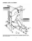
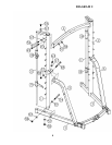
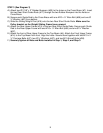
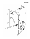
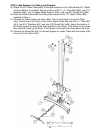
STEP 2 (See Diagram 2)
A.) Do not tighten Nuts and Bolts until instructed to do so.
B.) Attach the Left Upright Beam (#1) to the Left Rear Support (#5) and onto the left
Base Frame (#3).
C.) Secure it to the Base Frame with two M10 x 4” Allen Bolts (#54), four Ø ¾”
Washers (#57), and two M10 Aircraft Nuts (#58).
D.) Secure it to the Left Rear Support with one M10 x 4” Carriage Bolt (#48), one Ø
¾” Washer (#57), and one M10 Aircraft Nut (#58) from side. Secure with one M10
x 5/8” Allen Bolt (#63) and one Ø ¾” Washer (#57) from top.
E.) Repeat A to D to install the Right Upright Beam (#6) to the right Base Frame.
F.) Attach the Top Beam (#4) to the Left & Right Upright Beam. Secure each end of
the Top Beam to each Upright Beam with one 4” x 2 3/8” Curved Bracket (#23),
one M10 x 4 1/8” Allen Bolt (#53) and one Ø ¾” Washer (#57) to the upper hole,
one M10 x 4 1/8” Carriage Bolt (#49), one Ø ¾” Washers (#57), and one M10
Aircraft Nut (#58) to the lower hole.
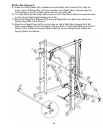
G.) Slide Lower Left Safety Stop Frame (#9) onto a Guide Rod (#11). Slide one
Safety Stop Frame (#18) onto the Guide Rod. Insert the bottom of the Guide Rod
into the hole on the left Base Frame. Attach the top of the Guide Rod to the
bracket on Left Upright Beam. Secure each end of Guide Rod with one M10 x ¾”
(#56) and one Ø ¾” Washer (#57). Repeat the same step to install the Lower
Right Safety Stop Frame (#10), the other Safety Stop Frame, and the other Guide
Rod to the other side.
H.) Turn and attach the hooks on the Lower Left & Right Safety Stop Frame to the
selected slot on Left & Right Upright Beam (#1 & #2).
7