


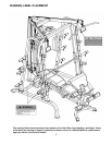
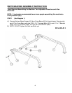
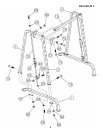

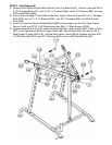
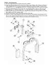
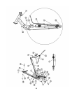
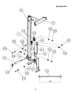
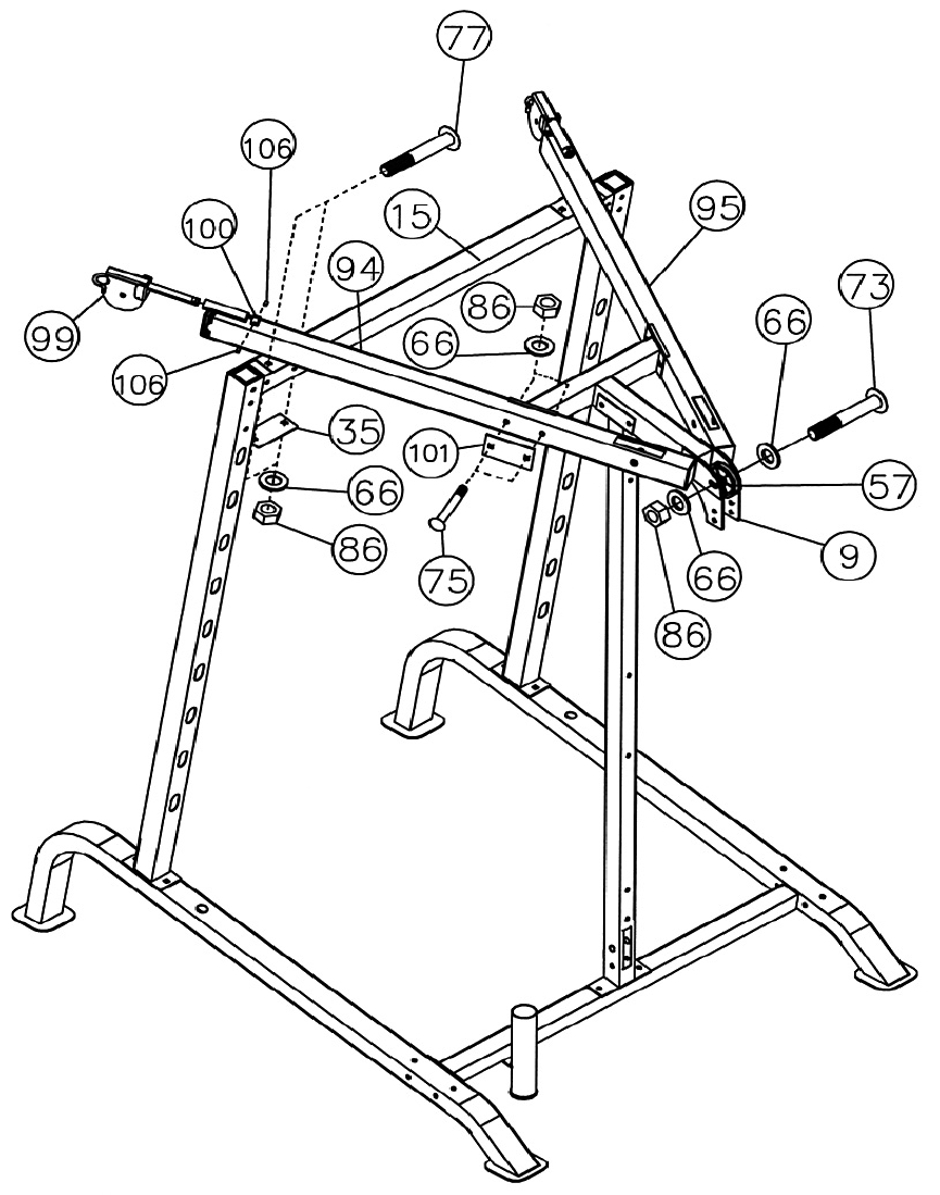
STEP 5 (See Diagram 5)
A. Place the Left Upper Frame (#94) onto the Front Top Beam (#15). Secure it with two M10 x
3 1/8” Carriage Bolts (#77), one 5 1/8” x 2” Bracket (#35), two Ø ¾” Washers (#66), and two
M10 Aircraft Nuts (#86).
B. Secure the Left Upper Frame (#94) to the Rear Upper Frame with two M10 x 2 ¾” Carriage
Bolts (#75), one 4 ¾” x 2 ¾” Bracket (#101), two Ø ¾” Washers (#66), and M10 Aircraft
Nuts (#86).
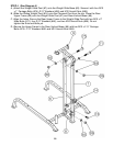
C. Insert a Cross-Over Swivel Pulley Bracket (#99) into the sleeve on the Left Upper Frame.
Secure it with one Ø 7/8” x 5/8” Bushing and two M6 x ¼” Allen Screws (#106).
D. Repeat procedures A, B and C above to install the Right Upper Frame (#95). Place a Pulley
(#57) in the opening on the Rear Upper Frame (#9). Secure the Pulley, the rear of Left &
Right Upper Frames (#94 & 95), and the Rear Upper Frame (#9) all together with one M10
x 3 3/8” Allen Bolt (#73), two Ø ¾” Washers (#66), and one M10 Aircraft Nut (#86).
11