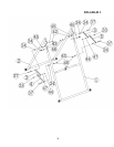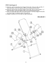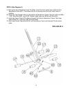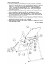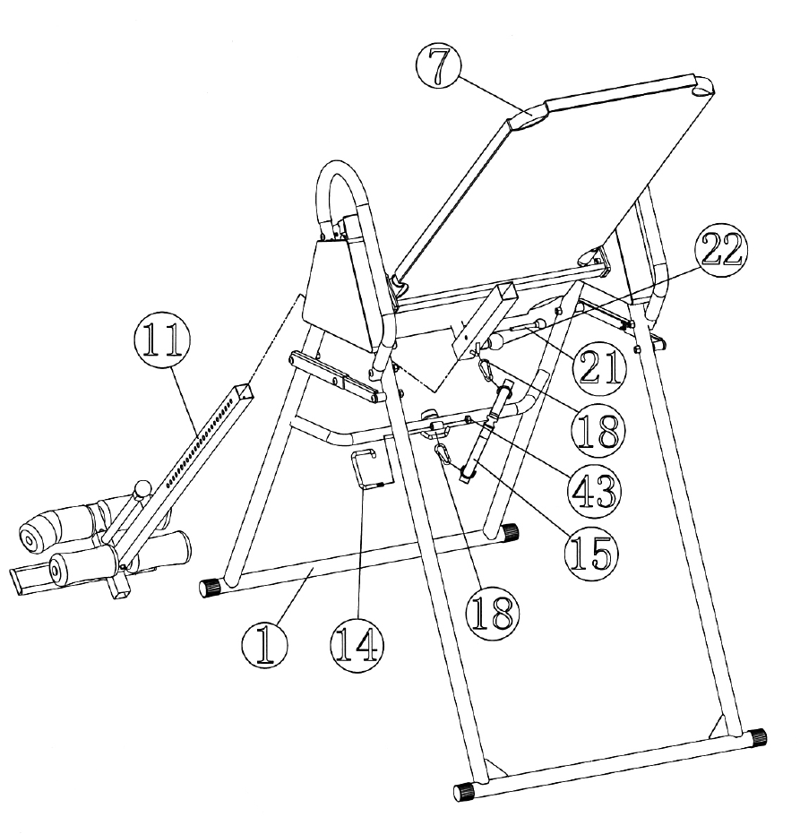
STEP 5 (See Diagram 5)
A.) Pull out the Backrest Adjustment Lock Pin (#22). Insert the Adjustment
Frame (#11) into the opening on the vertical frame on the back of Backrest
Frame (#7). Push back the Pin into the selected hole on Adjustment
Frame. The holes are scaled from 5’3” to 6’6”. User can select the
hole by user’s body height for better fitment while performing the
inversion exercises.
B.) Insert the Ring Lock Pin (#21) through the hole on the vertical frame and
hole on Adjustment Frame to securely lock the Adjustment Frame.
C.) Attach hook on Inversion Adjustment Belt (#15) to Front Support Frame
(#1) and to the vertical frame on Backrest Frame. Adjust the length of the
Belt to adjust the extension of inversion.
D.) Attach one side of U-shaped Lock Pin (#14) on front of Adjustment Frame,
insert the other side into hole on Front Support Frame and secure with one
M8 Aircraft Nut to lock Inversion Table for usage.
E.) When using the Inversion Table, remove the side of U-shaped Lock Pin off
from Adjustment Frame.
DIAGRAM 5
10


