


ASSEMBLY INSTRUCTION
Tools Required Assembling the Machine: Adjustable Wrench, Allen Wrench and
Hammer
NOTE: It is strongly recommended this machine to be assembled by two or more
people to avoid possible injury.
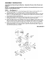
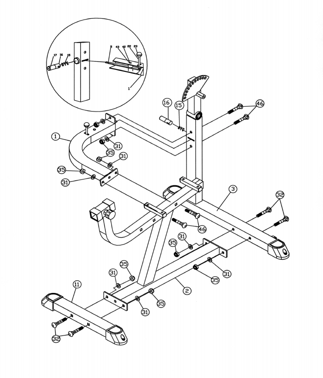
STEP 1 (See Diagram 1)
A.) Attach the Stabilizer (#11) to the Seat Support (#2). Secure it with two M10 x 3 ½”
Carriage Bolts (#32), ∅ ¾” Washers (#31) and M10 Aircraft Nuts (#35).
B.) Attach the Main Frame (#3) to the other end of Seat Support (#2). Secure it with two
M10 x 3 ½” Carriage Bolts (#32), ∅ ¾” Washers (#31) and M10 Aircraft Nuts (#35).
Do not tighten the nuts and bolts yet.
C.) Attach the Cross Brace (#1) to the Seat Support (#2). Secure it with two M10 x 2 ¾”
Carriage Bolts (#46), ∅ ¾” Washers (#31), and M10 Aircraft Nuts (#35).
D.) Attach the Spring (#15) to the Stopper (#16). Push the Stopper into the hole on the
post on the Main Frame. Align the slot on the Stopper with the open slot on the post.
Insert the Lever (#5) through the open slot on the post into the slot on the Stopper.
E.) Attach the Cross Brace (#1) to the Main Frame (#3). Secure it with two M10 x 2 ¾”
Carriage Bolts (#46), ∅ ¾” Washers (#31), and M10 Aircraft Nuts (#35). Tighten all
nuts and bolts previously installed.
DIAGRAM 1
4