


7
68
114
110
85
7
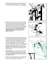
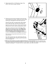
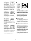
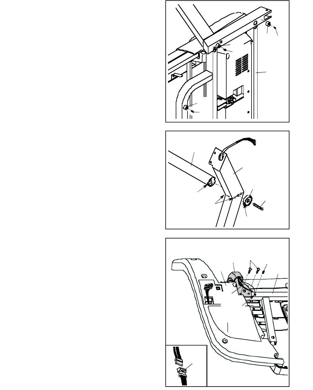
4. Turn the Console Base (85) upside-down; be careful not
to scratch the Console Base. Remove the bands and the
Console Back (not shown) from the Console Base. Hold
the ends of the Pulse Bar (110) against the Console
Frame (7) as shown. Note: The Pulse Bar Screws (68)
may be preattached and may need to be removed.
Connect the Pulse Wire (118) in the Console Base to the
pulse wire in the Pulse Bar (see the inset drawing). The
connectors should slide together easily and snap
into place. If the connectors do not slide together easily
and snap into place, turn one connector and try to con-
nect them again.
Open part bag B. Have another person hold the Pulse
Bar (110) firmly against the Console Frame (7). Attach
the Pulse Bar with four Pulse Bar Screws (68) (only two
are shown). Firmly tighten the Screws. Be careful not
to damage the wires.
Attach the ring on the ground wire to the Console Frame
(7) with a 1/2” Ground Screw (114). Note: There are no
wires on the other side of the Pulse Bar (110).
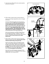
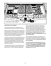
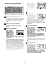
3. With the help of another person, raise the Right Upright
(82) and the Left Upright (not shown) to the vertical posi-
tion. Hold the Crossbar (90) between the Uprights, and
align the notches in the Crossbar with the indicated
welds on the Uprights. Attach each end of the Crossbar
with a 3/8” x 3 1/2” Bolt (81) and a Crossbar Endcap (84)
(only the right side is shown). Make sure that the
Crossbar Endcaps are turned so the notches are
aligned with the welds on the Uprights. Do not
tighten the Bolts yet.
82
90
81
84
Welds
Notch
Notch
Ground
Wire
118
118
3
4
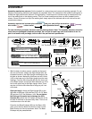
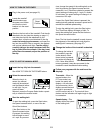
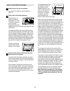
2. Attach the six Base Pads (100) (only three are shown) to
the bottom of the Base (109) with six 3/4” Tek Screws
(47). Note: The 3/4” Tek Screws are found in part bag C.
2
100
109
47
47
100
100
47