


ASSEMBLY
Assembly requires two persons. Set the treadmill in a cleared area and remove all packing materials. Do not
dispose of the packing materials until assembly is completed. Note: The underside of the treadmill walking belt is
coated with high-performance lubricant. During shipping, a small amount of lubricant may be transferred to the
top of the walking belt or the shipping carton. This is a normal condition and does not affect treadmill perfor-
mance. If there is lubricant on top of the walking belt, simply wipe off the lubricant with a soft cloth and a mild,
non-abrasive cleaner.
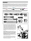
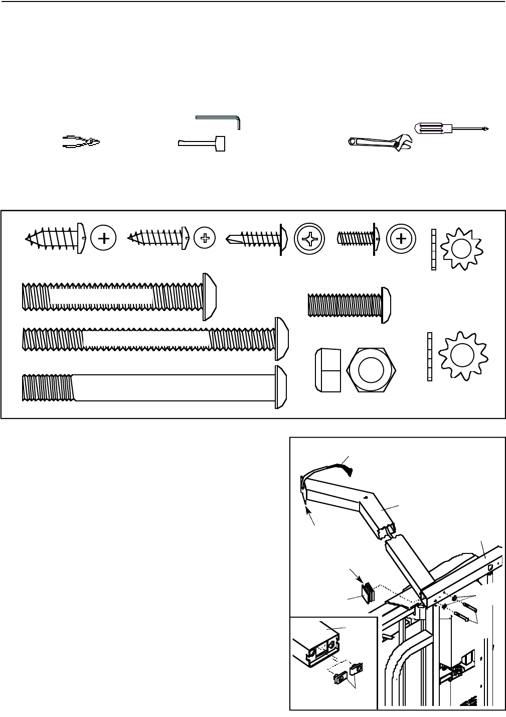
Assembly requires the included allen wrenches and your own phillips screwdriver ,
wire cutters , rubber mallet , and adjustable wrench .
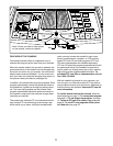
For help identifying assembly hardware, see the drawings below. Note: The assembly hardware and other
small parts are packaged in separate part bags. Do not open the part bags until instructed to do so. If a
part is not found in the part bags, check to see if the part has been preattached.
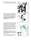
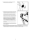
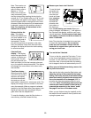
1. With the help of another person, carefully tip the tread-
mill onto its left side. Identify the Right Upright (82); the
indicated bracket on the Right Upright overhangs on the
left side as shown. Make sure that there are two U-Nuts
(105) in the lower end of the Right Upright (see the inset
drawing). Feed the Wire Harness (83) into the lower end
of the Right Upright, and pull the Wire Harness out of the
hole in the upper end of the Right Upright. Note: There
may be a tie on the Wire Harness to help you pull it out
of the hole.
Open part bag A. Attach the Right Upright (82) to the
right side of the Base (109) with two 5/16” x 3 1/2” Bolts
(93) and two 5/16” Star Washers (104). Do not tighten
the Bolts yet. Be careful not to damage the Wire
Harness (83). Attach the Left Upright (not shown) to the
left side of the Base in the same way. Note: There is not
a wire harness on the left side.
Press the two Base Endcaps (99) into the Base (109)
(only one is shown). Make sure that the notch in each
Base Endcap is at the top as shown. Note: The Base
Endcaps may be preassembled.
82
99
83
Bracket
Notch
109
104
93
1
105
82
Pulse Bar Screw
(68)–4
1” Bolt (71)–4
Wheel Bolt (107)–2
Wheel Nut (21)–2
3/4” Tek Screw (47)–6
1/2” Ground
Screw (114)–1
1/4” Star Washer
(92)–4
5/16” Star
Washer (104)–4
3/8” x 3 1/2” Bolt (81)–2
5/16” x 3 1/2” Bolt (93)–4
2” Bolt (92)–3
3” Bolt (56)–2
Star Washer (29)–2
3/4” Tek Screw
(3)–4
Wheel Nut (38)–2
Handrail Bolt (42)–4
Upright Bolt (65)–4
1/4” Washer
(38)–4
3/8” Washer
(66)–8
Wheel Bolt (36)–2
Star Washer (9)–6
(May be an internal Star Washer)
Extension Leg Screw (9)–2
Wheel Bolt (64)–2
1” Latch Screw (123)–2
3/4” Bolt (37)–6
Crossbar Screw
(53)–2
Washer (38)–4
Wheel Nut (13)–2
3” Bolt (70)–4
3/4” Screw (2)–8
1” Tek Screw
(58)–4
2” Bolt (64)–2
1” Bolt (37)–6
Crossbar Screw
(39)–2
Silver Ground
Screw (75)–1
1/2” Silver Screw
(48)–1
Star Washer
(63)–4
3/4” Screw (6)–20
1” Silver Screw (92)–2 1 1/2” Screw (93)–2
Internal Star
Washer (72)–6
1 1/4” Bolt (104)–4 Wheel Bolt (107)–2
2” Silver Screw (93)–2
1 1/4” Screw (92)–2
3/4” Bolt (71)–2
Star Washer
(106)–4
Handrail Washer
(69)–2
4 1/2” Bolt (104)–4
3/4” Screw (6)–10
6