


8
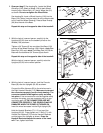
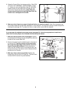
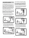
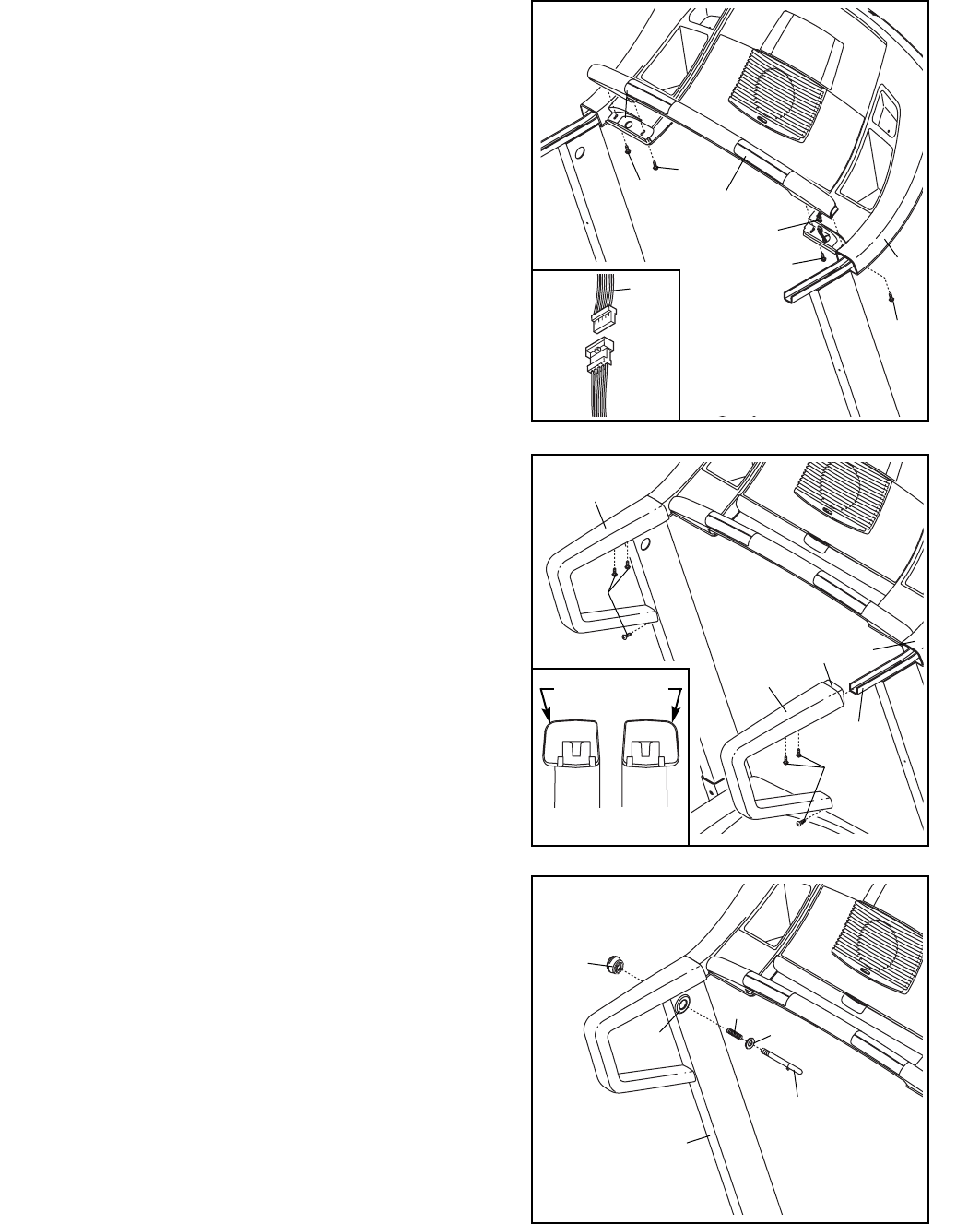
6. Identify the Left and Right Handrails (68, 81) (see the
end views of the Handrails in the inset drawing). The
curved edges of the Handrails should be on the outside.
Slide the Right Handrail (81) onto the Right Handrail
Bracket (113), and press the lip on the front of the Right
Handrail under the Console Base (85). (Note: It may be
helpful to tip the Right Handrail and to tap it with a rub-
ber mallet to correctly position it.) Tighten three 3/4”
Screws (6) into the Right Handrail as shown. Note: It
may be necessary to move the lower end of the Right
Handrail slightly to align the lower screw hole.
Attach the Left Handrail (68) in the same way.
See assembly step 1. Tighten the four 1 1/4” Bolts
(104).
113
81
Lip
85
68
6
6
6
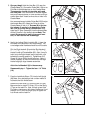
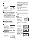
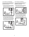
7. Press the Latch Knob Sleeve (75) into the Left Upright
(69). Note: It may be helpful to use a rubber mallet to
fully insert the Latch Knob Sleeve.
Remove the Latch Knob (70) from the Latch Pin (80).
Make sure that the Latch Pin Collar (76) and the Spring
(77) are on the Latch Pin. (Note: If there are two Latch
Pin Collars, place one on each side of the Spring.) Insert
the Latch Pin into the Left Upright (69) and tighten the
Latch Knob onto the Latch Pin.
80
76
75
69
77
7
70
(81)
Curved Edge
(68)
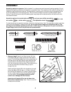
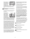
5. Open part bag A. Hold the Pulse Bar (125) near the
Console Base (85). Connect the Pulse Wire (124) on the
Pulse Bar to the indicated wire on the Console Base.
The connectors should slide together easily and
snap into place. If the connectors do not slide together
easily and snap into place, turn one connector and try to
connect them again. Insert the wires into the hole in the
Console Base.
Have a second person hold the Pulse Bar (125) firmly on
the Console Base (85). Attach the Pulse Bar to the
Console Base with two 1 1/4” Screws (92) in the loca-
tions shown. Be careful not to damage the Pulse
Wire (124) or the wire on the Console Base. Next,
tighten two 2” Silver Screws (93) into the Console Base
and the Pulse Bar in the locations shown. Note: The
correct Screws must be used in the correct loca-
tions, or the Pulse Bar may be damaged.
92
85
125
5
92
93
124
93
124