


69
82
113
73
83
71
71
72
72
4
85
83
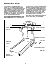
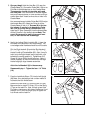
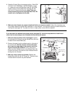
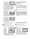
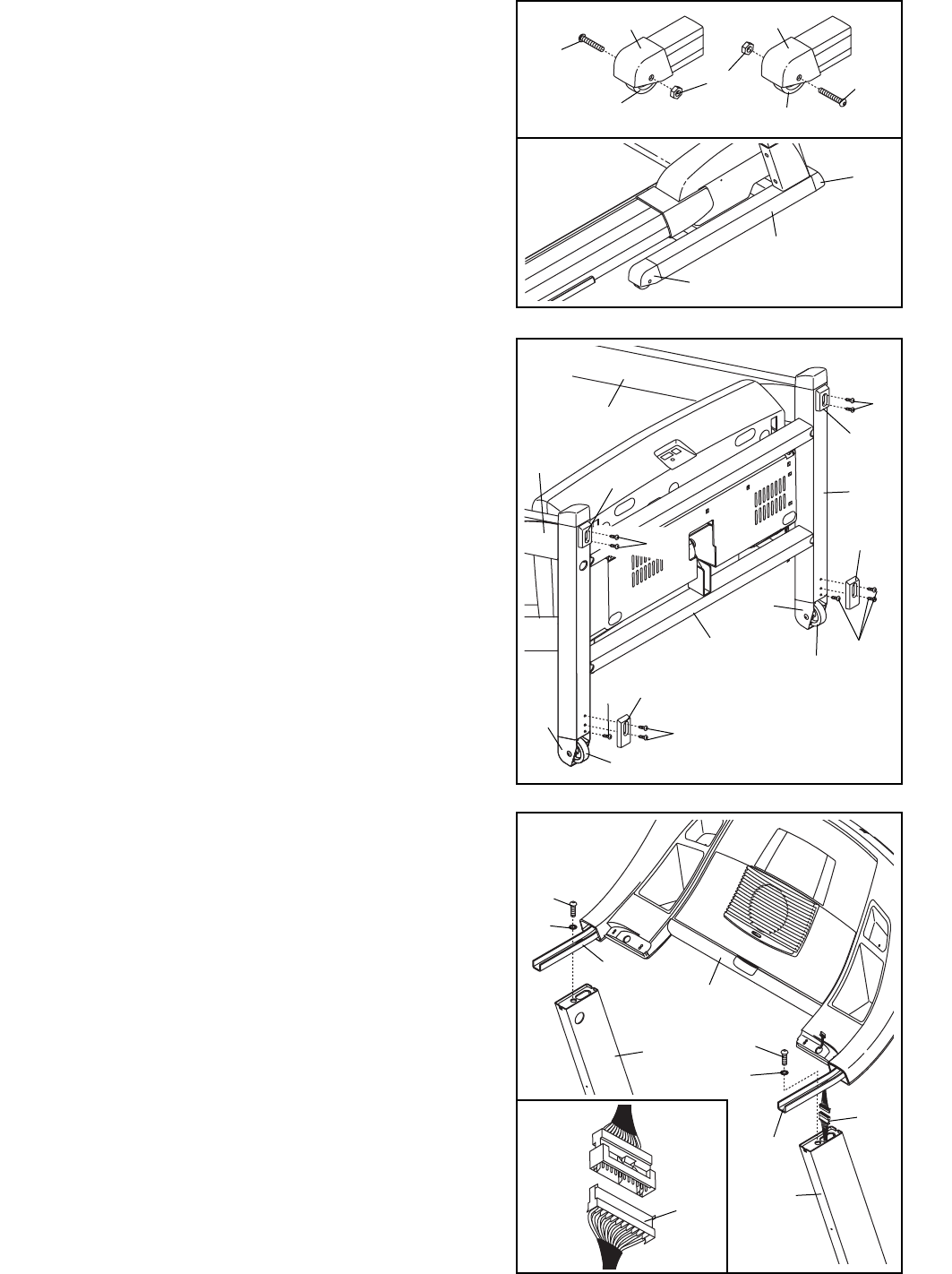
4. With the help of a second person, hold the Console
Base (85) near the Uprights (69, 82) as shown.
Connect the Wire Harness (83) to the wire harness in
the Right Handrail Bracket (113). Make sure to connect
the connectors properly (see the inset drawing). The
connectors should slide together easily and snap
into place. If the connectors do not slide together easily
and snap into place, turn one connector and try to con-
nect them again. IF THE CONNECTORS ARE NOT
CONNECTED PROPERLY, THE CONSOLE MAY BE
DAMAGED WHEN THE POWER IS TURNED ON.
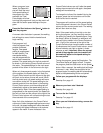
Insert the wires harnesses into the Right Upright (82).
Hold the Handrail Brackets (73, 113) on top of the
Uprights (69, 82). Finger tighten two 1” Bolts (71) with
Internal Star Washers (72) into the Handrail Brackets
and the tops of the Uprights as shown. Press the
Handrail Brackets towards the center of the tread-
mill. Then, tighten both Bolts.
7
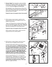
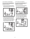
3. With the help of a second person, carefully tip the
Uprights (69, 82) down so the treadmill pivots on the
Wheels (108) as shown.
Tighten a 3/4” Screw (6) into one side of the Base (109)
and one of the Wheel Housings (106). Attach a long Rear
Base Pad (105) and a short Front Base Pad (100) to the
Base with four additional 3/4” Screws (6) as shown.
Repeat this step on the opposite side of the treadmill.
With the help of a second person, carefully raise the
Uprights (69, 82) to the vertical position.
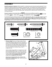
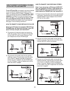
2. Open part bag C. See drawing 2a. Locate the Wheel
Housings (106). Attach a Wheel (108) to each Wheel
Housing with a Wheel Bolt (107) and a Wheel Nut (21)
as shown. Do not overtighten the Wheel Bolts.
See drawing 2b. Insert a Wheel Housing (106) into the
Base (109). (Note: It may be helpful to use a rubber mallet
to fully insert the Wheel Housing.) Press a Base Endcap
(99) onto the end of the Base.
Repeat this step on the opposite side of the treadmill.
100
105
105
109
106
106
106
108
21
6
6
106
108
106
99
99
107
107
2a
2b
108
108
109
69
82
3
6
6
100
6