


8
Small
Hole
71
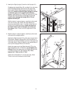
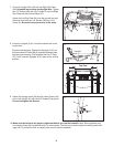
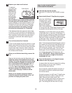
4. Hold the Console Base (47) near the Left Handrail (71).
Attach the end of the ground wire on the Console Base
t
o the indicated small hole in the Left Handrail with the
Silver Ground Screw (75).
47
75
G
round
W
ire
42
5. Touch the Right Handrail (72) to discharge any static.
Slide the sleeve off the connector on the Upright Wire
(42) as shown in the inset drawing. Next, press the end of
the Upright Wire into the socket in the bottom of the
Console Base (47).
The connector should slide easily
into the socket and snap into place. If the connector
does not slide easily and snap into place, turn the connec-
tor and then insert it. Then, slide the sleeve back over the
connector.
72
47
4
5
47
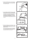
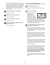
6. Set the Console Base (47) on the Handrails ( 71, 72).
Attach the Console Base with four 3/4” Screws (2). Start
all four Screws before tightening them; do not over-
tighten the Screws.
See the lower drawing. Make sure that the Upright Wire
(42) is routed below the two indicated round posts (A).
Next, press the Upright Wire into the slot between the
square post (B) and the Console Base (47).
2
2
A
B
72
71
6
42
Sleeve
Connector
47
42