


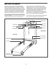
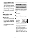

ASSEMBLY
Assembly requires two people. Set the treadmill in a cleared area. Do not remove the packing material from
the area shown in drawing 2. Remove all other packing materials. Do not dispose of the packing materials until
assembly is completed. Treadmill assembly requires the included allen wrench your own phillips screw-
driver and 9/16” wrench .
Note: The underside of the treadmill walking belt is coated with high-performance lubricant. During shipping, a
small amount of lubricant may be transferred to the top of the walking belt or the shipping carton. This is a normal
condition and does not affect treadmill performance. If there is lubricant on top of the walking belt, simply wipe off
the lubricant with a soft cloth and a mild, non-abrasive cleaner.
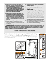
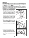
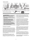
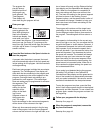
2. Remove the packing material from the area shown.
Attach the Storage Latch Assembly (33) and the Latch
Spacer (35) to the left Upright (109) with two Latch
Screws (34) as shown. Be careful not to overtighten
the Latch Screws.
Thread the Console Latch (55) into the right Upright (109).
109
109
33
34
55
35
Packing
Material
Felt
Felt
2
6
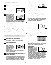
1. See drawing 2. Leave in place the packing material
shown in the indicated area until step 1 is completed.
While a second person holds one end of the treadmill,
carefully tip the treadmill onto its side as shown. Using the
included allen wrench and a 9/16” wrench, attach the two
Extension Legs (70) to the base of the Uprights (109) with
the four Bolts (71) and Nuts (68). Make sure that the
Extension Legs are turned so the Base Pads (66) are in the
positions shown.
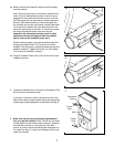
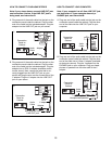
With the help of a second person, carefully raise the tread-
mill to the vertical position, and then lower the Walking
Platform (93) to the floor. Note: If the treadmill rocks slightly,
tip the treadmill back onto its side, loosen the four Nuts (68),
adjust the positions of the Extension Legs (70), and then
retighten the Nuts. Raise the treadmill back to the vertical
position. Repeat until the rocking motion is eliminated.
71
109
93
68
70
66
71
68
70
66
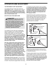
1
43
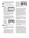
39
55
3. Pull the Console Latch (55) to the right, and rotate the
Console Base (43) to the position shown. Release the
Console Latch, making sure that the Console Base is
locked in place. Note: It may be helpful to push down on
the right Handrail (39) and push the Console Latch into
the locked position.
Note: If the Handrail (39) rocks, attach one or two pieces
of the included felt onto the bracket in the locations shown
in drawing 2.
3