


7
68
5
Collar
Spring
143
55
Knob
132
3
Small
Holes
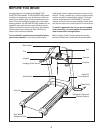
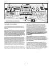
3. With the help of a second person, raise the treadmill
F
rame (55). Hold the Latch Housing (68) and the Latch
Housing Cover (5) against the sides of the Frame as
shown. Loosely thread the two blunt-tipped 1/2” Screws
(132) into the Latch Housing Cover and the Latch Housing
as shown. Do not tighten the Screws yet.
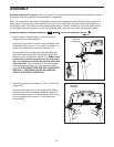
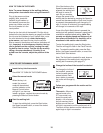
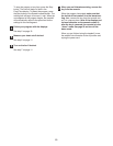
Remove the knob from the pin. Make sure that the collar
a
nd the spring are on the pin. The collar should be on the
side of the spring shown. Insert the pin into the Latch
Housing (68), and tighten the knob back onto it.
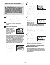
Align the pin with the hole in the Left Handgrip (140) by
sliding the Latch Housing (68) up or down. Make sure that
the pin can be inserted fully into the hole. Hold the Latch
Housing in place as you tighten two 1/2” Tek Screws (143)
into the Latch Housing and the Frame (55). Then, tighten
the 1/2” Screws (132). Note: It may be necessary to pull
on the knob to access and tighten the Screws.
5. Make sure that all parts are properly tightened before you use the treadmill. Place a mat beneath the
treadmill to protect the floor or carpet. For your benefit, we recommend that you familiarize yourself with
the TROUBLESHOOTING section on pages 26 and 27.
Hole
Pin
140
143
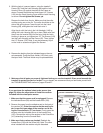
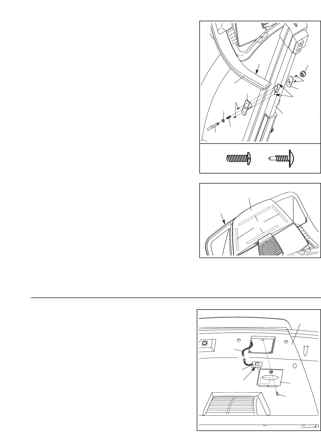
If you purchase the optional chest pulse sensor (see
page 23), follow the steps below to install the receiver
included
with the chest pulse sensor.
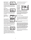
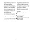
1. Make sure that the power cord is unplugged. Remove
the indicated Screw (40) and the Access Door (135).
2. Remove the paper from the adhesive pad on the back of
the receiver (A).
Orient the receiver so the small cylin-
der is near the lower edge of the receiver and is fac-
ing the Console Back (117) as shown. Firmly press the
receiver onto the indicated corner of the Access Door
(135). Connect the wire on the receiver to the Pulse Wire
(101) extending from the Console Back.
3.
Make sure that no wires are pinched. Reattach the
Access Door (135) with the Screw (40). Note: The other
wires included with the receiver may be discarded.
A
117
135
Cylinder
40
101
132
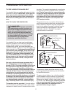
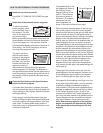
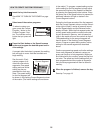
4. Remove the backing from the indicated tape on the con-
sole assembly. Press the Book Holder (142) firmly onto
the tape. Note: The Book Holder may be preassembled.
Console
Assembly
142
Tape
4