7
06/03 P/N 211543B
8
11
49
16
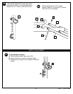
10.
11.
17
30
24
52
51
49
30
12.
49
8
55
54
54
57
44
57
55
13.
48
8
46
45
26
47
25
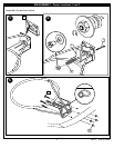
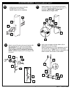
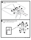
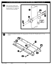
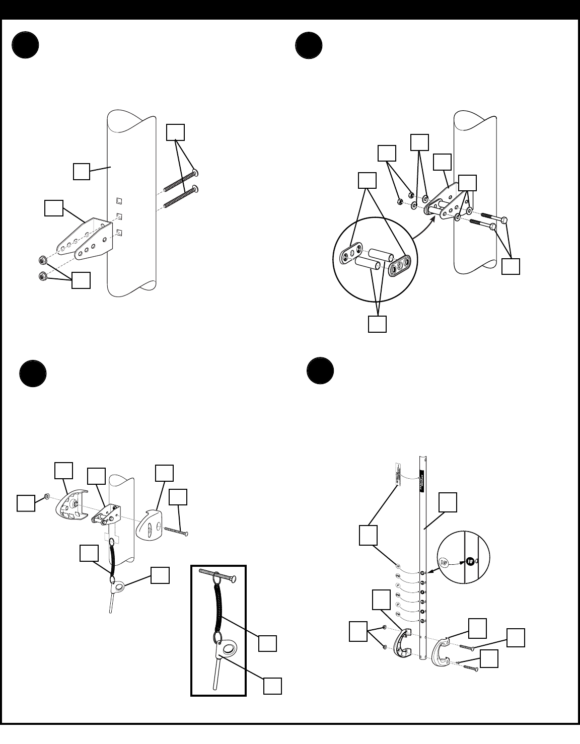
Install pole mount bracket (49) with
carriage bolts (16) as shown.
Tighten flange nuts (8) completely.
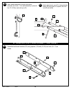
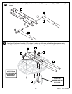
Attach spacers (51, 52) to pole mount bracket
(49) with bolts (24), washers (30), and nuts (17)
as shown. IMPORTANT! Tighten until
washers (30) no longer move.
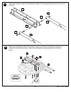
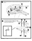
Attach covers (54) onto pole mount bracket (49)
with carriage bolt (31) and nut (8) as shown.
IMPORTANT! Loop end of pin lanyard (57)
over carriage bolt (31) during this assembly.
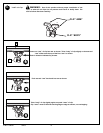
NOTE: Assemble lanyard (57) to locking pin (55)
as shown.
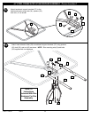
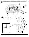
Apply logo and height indicator labels (48) to
adjustment rod (47) as shown.
Attach handle parts (45, 46) to adjustment rod (47)
with screw (26), carriage bolts (22), and flange
nuts (8) as shown. NOTE: Holes in adjustment rod
allow for either rear access or side access.
ELEVATOR ASSEMBLY - Corner Locations 1 and 3


