


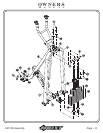
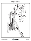
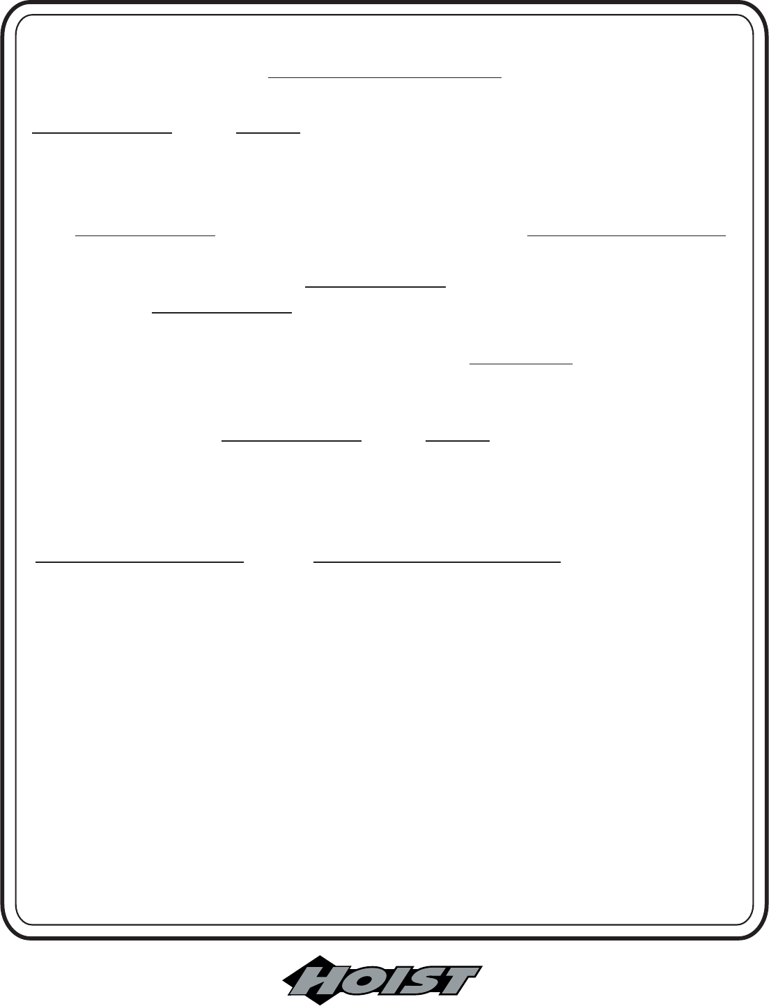
FRAME ASSEMBLY
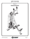
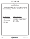
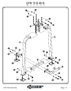
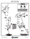
Step 2c
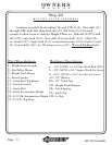
6 - Front Upright
8 - Resistance Lever Arm
9 - Weighted Connector
10 - Arm
11 - Handle Assembly
12 - Bearing Housing
Part Descriptions
C - 1/2”-13UNC x 3 1/4” Hex Head Bolt (WZ)
E - 1/2”-13UNC x 6” Hex Head Bolt (WZ)
F - 3/8”-16UNC x 3/4” Button Head Bolt (WZ)
R - 3/8”-16UNC x 1” Socket Head cap Screw
AA - 1/2” Washer
AB - 3/8” Washer
AE - 3/8” Lock Washer
BA - 1/2” Nylok Nut
CS - 19mm dia. x 57.5mm lg. Axle
CE - 25.4mm dia. x 120mm lg. Axle
CF - Rubber Sleeve
CG - Aluminum Bolt on Cap
Hardware Descriptions
Page - 9
HD1700 Assembly
OWNERS
MANUAL
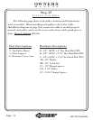
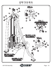
Continue assembly by inserting (CE) into (6), then attach (10) to (CE).
bolts. Check to see that the Arm Assembly rotates
freely. If not, turn back the nut on the bolt for the axle just enough so that the
Arm Assembly rotates freely. Slide a (CF) onto each tube end of (10). Then
install an (11) to each side capturing (CF) between (11) and Button Head Bolt
(F). bolts. Slide a (12) onto each (11).
for the correct rear slot positioning of (12). Install the range limiting bolt (F)
through the slots in each (12). bolts. Attach (CG) to the top
of each (12). the retaining nuts then turn the nuts back just
enough so that each (12) rotates freely. Now insert both (CS)’s into (9), then
attach to (10) at the top and to (8) at the bottom. when attaching
(9) to (10), take special precaution when handling the arm. If released, the
front of (10) will swing up with a considerable amount of force, and could
cause bodily injury. bolts.
Wrench Tighten NOTE:
Wrench Tighten See the Assembly Note
Wrench Tighten
Wrench Tighten
WARNING:
Wrench Tighten NOTE: Check to see that the Arm
Assembly and the Weighted Connector rotates freely. If not, turn back the nut
on the bolt for the axle just enough so that the Arm Assembly and Weighted
Connector rotates freely.