


29 of 39
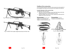
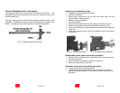
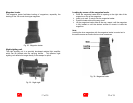
Disassembly of the bolt
¾ Push the cross pin to the left (e.g. with gas piston) and detach.
¾ Remove the firing pin to the rear.
¾ Take out the control bolt to the left.
¾ Detach the bolt head to the front.
Assembly of the bolt
¾ Slide the bolt head with the extractor pointing to the right from the
front into the bolt head carrier.
¾ Insert the control bolt from the left into the bolt head carrier and the
bolt head; mind that the flat surfaces on the control bolt are parallel
to the firing direction.
¾ Introduce the firing pin from the rear into the bolt head carrier and
the bolt head.
¾ Insert the cross pin from the left side into the bolt head carrier.
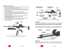
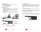
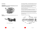
Fig. 39: Remove the push rod
Fig. 40: Take out the gas piston
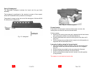
Fig. 41: Bolt, disassembled
10 of 39
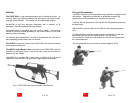
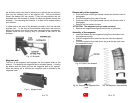
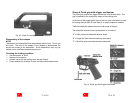
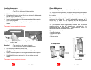
Group 2 Bolt assembly
The bolt assembly with the rotary bolt head is guided in the receiver.
The bolt assembly is driven by the gas piston and the recoil spring and
serves for feeding of the cartridges, locking of the chamber, cartridge
ignition, case extraction and ejection as well as for cocking of the
hammer.
The bolt head is retained in the bolt head carrier by the control bolt which
also controls its rotary movement
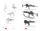
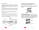
At its front the bolt head is provided with locking lugs. The spring-loaded
extractor is located in a gap between the locking lugs. Adjacent to the
extractor there is the sprig-loaded ejector.
The firing pin is retained by the cross pin.
A cocking lever on the front end of the bolt head carrier can be swiveled
to the left and to the right for actuation by both left and right handed
firers.
Fig. 12: Bolt assembly