


7 of 39
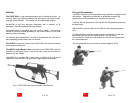
DESCRIPTION OF THE ASSEMBLY GROUPS
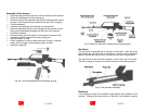
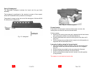
Group 1 Receiver with barrel, buttstock and attaching parts
The receiver is made of high-strength fiber-reinforced plastics. It houses
all the other assembly groups. Inside the receiver there are guideways
for the bolt as well as contact surfaces for the pistol grip, the backplate
and the magazine well.
The barrel is fastened and centered to the receiver by means of a nut.
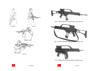
The flash hider is screwed onto the muzzle. Behind the flash hider there
is the bayonet mount with rifle grenade guide which is fastened by
means of a cross pin. The gas block behind the bayonet mount is also
fastened by means of a cross pin.
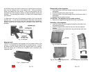
The carrying handle integrates the optical sight and a mechanical
emergency sight. The carrying handle is mounted onto the guideway on
top of the receiver and fastened there by means of three screws.
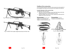
On the right side of the receiver there is the ejection port with the
cartridge case deflector. The cartridge case deflector directs the ejected
cases and also serves as a catch for the folded buttstock.
Handguard, magazine well and pistol grip are fitted to the bottom of the
receiver by means of locking pins.
At the rear of the receiver there is the hinge for the folding buttstock.
32 of 39
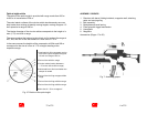
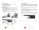
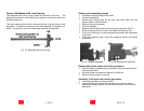
Adjustment of the optical sight
If a sight adjustment becomes necessary, this may be done by vertically
or horizontally adjusting the optical sight.
Height adjustment:
¾ If the weapon’s point of impact is too high, turn the upper adjusting
screw counter-clockwise in the “T” direction.
¾ If the weapon’s point of impact is too low, turn the upper adjusting
screw clockwise in the “H” direction.
Side adjustment:
¾ If the weapon’s point of impact is too far to the right, turn the lateral
adjusting screw counter-clockwise in the “L” direction.
¾ If the weapon’s point of impact is too far to the left, turn the lateral
adjusting screw clockwise in the “H” direction.
Note:
One graduation changes the point of impact by approx. 2.3 cm at a
range of 100 m.
Fig. 46: Adjusting screws