


5
ASSEMBLY
Assembly requires two persons. Place all parts of the elliptical crosstrainer in a cleared area and remove the
packing materials. Do not dispose of the packing materials until assembly is completed.
The following tools are required for assembly: a phillips screwdriver , an adjustable
wrench , a rubber mallet , and pliers .
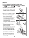
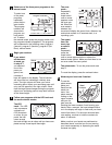
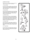
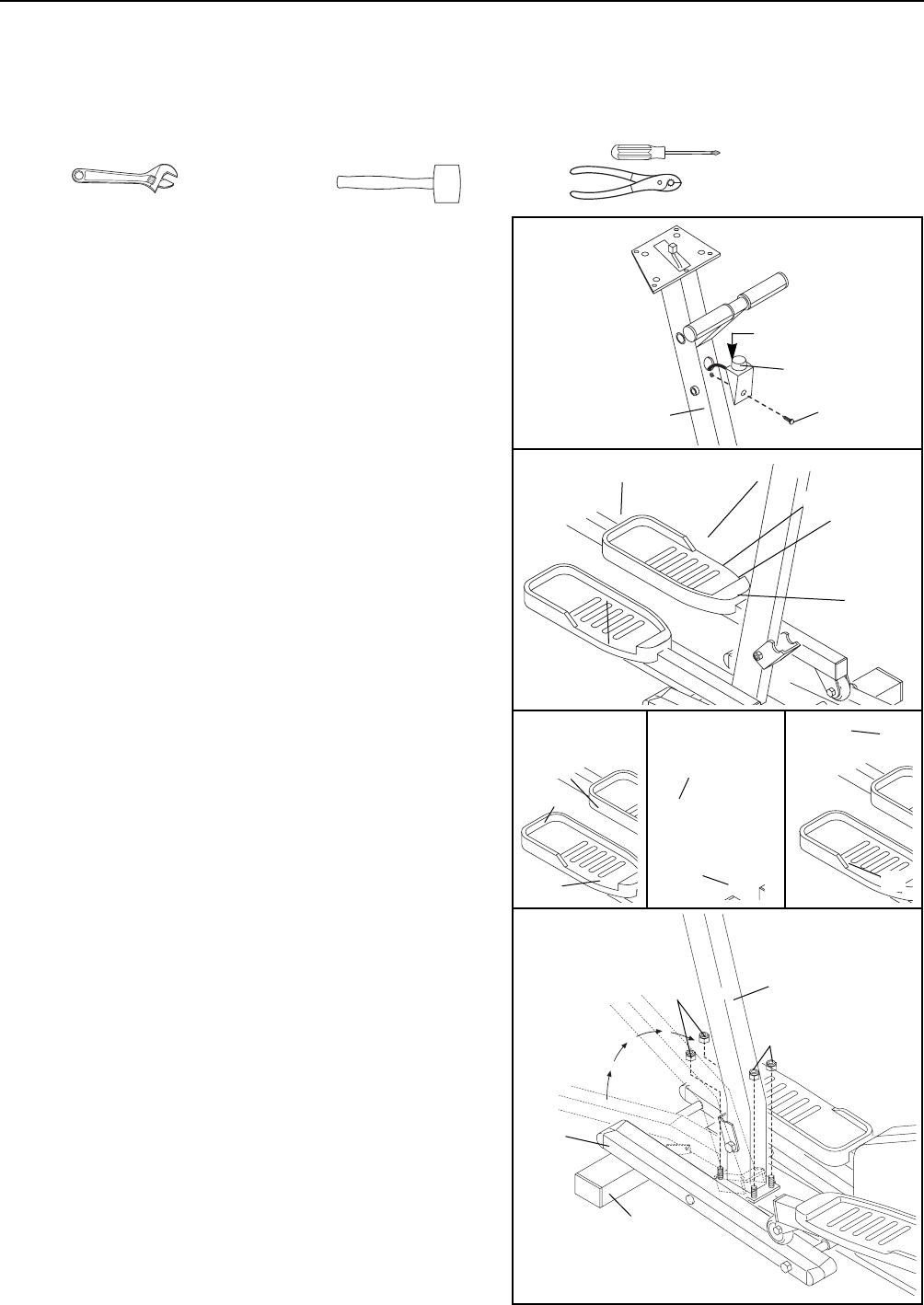
2. Lay a cloth over the front of the Frame (1) to protect it.
Lay the Upright (2) in the position shown. Connect the
Extension Wire (51) to the Reed Switch Wire (50).
Next, connect the Resistance Cable (57) to the
Extension Cable (93) in the following way:
¥ Refer to drawing A. Pull up on the metal bracket, and
insert the tip of the Resistance Cable (57) into the
wire clip on the Extension Cable (93) as shown.
¥ Refer to drawing B. Firmly pull the Resistance Cable
(57) and slide it into the metal bracket on the
Extension Cable (93) as shown.
¥ Refer to drawing C. Using pliers, squeeze the prongs
on the upper end of the metal bracket together.
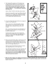
3. Align the two holes in the front of the Upright (2) with
the two welded bolts in the front of the Frame (1).
Carefully push the Reed Switch Wire (not shown) into
the Upright until there is no slack.
Next, pivot the Upright (2) about halfway to the vertical
position while guiding the Split Plastic Sleeve (not
shown) into the Upright. Once the top edge of the Split
Plastic Sleeve is inside the Upright, pivot the Upright
to the vertical position so it rests on the four welded
bolts on the Frame (1). Be careful to avoid pinching
the wires.
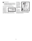
Lift the front of the Incline Frame (5). Tighten a 3/8Ó
Nylon Locknut (26) onto each welded bolt.
Refer to assembly step 1. Insert the tab on the Resis-
tance Control (57) into the Upright (2). Next, press the
bottom of the Resistance Control against the Upright.
Tighten the Housing Screw (33) into the Resistance
Control and the Upright.
2
2
1
93
93
93
57
57
Metal
Bracket
57
51
B
3
26
2
1
5
26
50
A
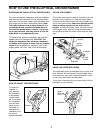
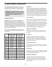
1. Turn the Resistance Control (57) counterclockwise to
the minimum setting.
If the Resistance Control (57) is attached to the Upright
(2), remove the Housing Screw (33). Pull the bottom of
the Resistance Control away from the Upright and then
slide it down to remove it.
C
93
57
1
57
Tab
2
33