


SKU 94142 For technical questions please call 1-800-444-3353. Page 3
9. Use the right Tricycle for the situation. There are certain applications for which this
Tricycle was designed. Do not modify this Tricycle and do not use this Tricycle for a
purpose for which it was not intended.
10. Only one person allowed on the Tricyle at any time. Only one seated rider should be on the
Tricycle at a time. No other passengers should be standing on the rear of the frame, or sitting
on the handlebars.
11. The Tricycle is meant for off-road use and is not for use as transportation on main
streets and highways.
12. Do not exceed the maximum weight capacity of 250 Lbs.
13. Always make sure tires are properly inflated (see page 2).
WARNING: The warnings, cautions, and instructions discussed in this instruction manual cannot
cover all possible conditions and situations that may occur. It must be understood by
the operator that common sense and caution are factors which cannot be built into
this product, but must be supplied by the operator.
Unpacking
When unpacking your Tricycle with Pneumatic Tires, check to make sure all parts listed on page 5
are included. If any parts are missing or broken, please call HARBOR FREIGHT TOOLS at
1-800-444-3353.
Assembly
Your Rolling Tricycle with Pneumatic Tires will require complete assembly. It is important that you
read the entire manual to become familiar with the product BEFORE you assemble and use the
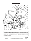
Tricycle. Before assembling the Tricycle be sure that you have all parts described in the Parts List
and Assembly Diagram located on the last pages of this manual.
THE RIDER OF THE TRICYCLE MUST BE AT LEAST 48” TALL TO PROPERLY REACH THE PEDALS.
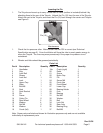
Handlebars
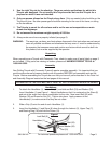
1. To attach the Handlebar (1), loosen Nut (31) and slide out Bolt (33) and Washer (32).
Insert Handlebar (1)-see Figure 1. Adjust Handlebar so that it is centered on the Stem (8)
and set at the angle that is most comfortable for the rider. Now insert Bolt (33) with
Washer (32) and thread on Nut (31). Tighten into place. Apply pressure to the
Handlebars(1) to make certain that they do not rotate.
2. Slide a Grip (2) onto the end of each Handlebar (1).
3. Insert the Handlebar (1) and Stem (8) down through the Locknut (5), Upper Cap (7),
and Bearing Ring (36) and into the Frame (13).
Lock Bolt (3)
Bolt (33)
Nut (31)
Washer (32)
Handlebar (1)
Figure 1
Stem (8)